A cable joint fire protection system and its implementation method

A technology for cable joints and fire protection systems, which is applied in the direction of cable joints, electrical components, instruments, etc., and can solve problems such as unconsidered, no anti-fire prevention measures for cable joint protective boxes, and no early warning treatment measures, etc.

Active Publication Date: 2021-08-31
应急管理部天津消防研究所
View PDF7 Cites 0 Cited by
  • Summary
  • Abstract
  • Description
  • Claims
  • Application Information

AI Technical Summary

Problems solved by technology

[0004] 1. Most cable joint protective boxes are not equipped with fire prevention measures
[0005] 2. The protection of the cable joint is not complete, and it is not considered that once the cable joint catches fire and explodes, it is easy to ignite other combustibles near the cable joint
[0006] 3. There is no early warning and pretreatment function for the cable joint, and it can only be processed after the fire and explosion of the cable joint, which has missed the best processing time
[0010] The disadvantage of this patent is that there is no early warning and treatment measures in this patent, which cannot realize early warning and treatment of cable joint failure; there is no explosion vent chamber in the patent, and the explosion and fire caused by cable joint failure cannot be limited within the protective box; the patent There is no fire extinguishing device outside the protective box, which cannot prevent the fire from spreading after the cable joint explodes and catches fire

Method used


Image

  • A cable joint fire protection system and its implementation method
  • A cable joint fire protection system and its implementation method
  • A cable joint fire protection system and its implementation method

Examples


Embodiment Construction

[0036] In order to understand the present invention more clearly, describe in detail in conjunction with accompanying drawing:

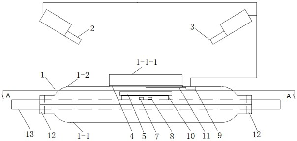
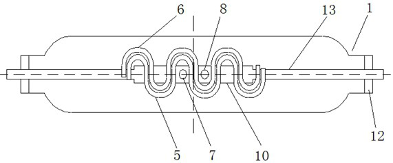
[0037] like Figure 1 to Figure 4 As shown, a cable joint fire protection system includes cable joint protective box 1, fire extinguishing device Ⅰ2, fire extinguishing device Ⅱ3, waterproof and ventilating component 4, fire extinguishing pipe Ⅰ5, fire extinguishing pipe Ⅱ6, temperature detector Ⅰ7, temperature detector Ⅱ8, magnetic generator The component 9 and the cable 13 also include a fire extinguishing pipe support 10 and a magnetic generator starting rope 11 .

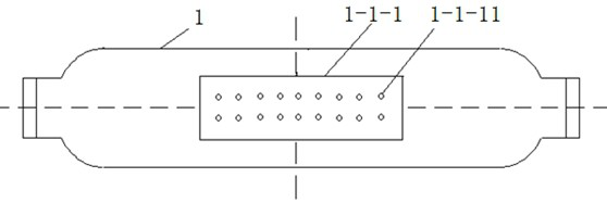
[0038] The cable joint protection box 1 is composed of an upper shell 1-1 and a lower shell 1-2. The upper shell 1-1 is provided with a rectangular explosion venting chamber 1-1-1, and a rectangular explosion venting chamber 1-1- 1. It communicates with the inside of the upper shell 1-1, and two rows of several exhaust holes 1-1-11 are symmetrically arranged on the surface of the rect...


PUM


Abstract

The invention relates to a cable joint fire protection system and its implementation method. An explosion vent chamber is provided outside the upper casing, and several exhaust holes are arranged on the surface of the explosion vent chamber; waterproof and breathable components are fixed along the periphery of the explosion vent chamber in the upper casing. , the magneto-generating element is fixed in the upper case, and the magneto-generating element is connected to the waterproof and ventilating component through the magneto-generating starting rope; the cable with the joint is placed in the lower case, and the fire-extinguishing pipe bracket is arranged above the cable joint, and the fire-extinguishing pipe I and The fire extinguishing pipe II is fixed on the fire extinguishing pipe bracket, the temperature detector I and the temperature detector II are arranged on the upper surface of the cable joint; the upper shell and the lower shell are fixed, and the magnetic generating element is respectively connected with the fire extinguishing device I and the fire extinguishing device II , The fire extinguishing device I and the fire extinguishing device II are respectively arranged above the protective box of the cable joint. Before the cable joint is in danger, a fire signal is issued, and fire extinguishing measures are implemented for the joint. At the same time, the fire extinguishing device outside the protective box is linked to implement fire extinguishing protection measures for the area near the cable box.

Description

technical field [0001] The invention relates to fire-fighting facilities, in particular to a cable joint fire-fighting system and a realization method, which are used to effectively prevent and control fires at cable joints and protect the safety of cable joints and cable corridors. Background technique [0002] In recent years, the number of fires caused by electricity has increased year by year, and the majority of fires are caused by cable joint failures. Cable joint failures are frequent faults in cable tunnels and are also the culprit of fires in cable tunnels. The cable joint is broken down due to the insulation drop caused by the outside world or its own quality reasons. The cable joint explodes and catches fire, which burns the cables and equipment, resulting in power outages, long repair time, delays in production, and heavy direct and indirect economic losses. Serious cause casualties. [0003] The following problems exist in the use of traditional cable joint pro...

Claims


Application Information

Patent Timeline
Patent Type & Authority Patents(China)
IPC IPC(8): H02G15/10H02G3/08H02G3/03A62C3/16A62C37/11A62C37/40G08B21/18
CPCA62C3/16A62C37/11A62C37/40G08B21/18H02G3/03H02G3/088H02G15/10
Inventor 高云升伊程毅盛彦锋马建琴刘连喜羡学磊甘晓虹
Owner 应急管理部天津消防研究所
Why Eureka
Try Eureka