Power factor correction circuit

一种功率因子校正、电路的技术,应用在输出功率的转换装置、交流功率输入变换为直流功率输出、电气元件等方向,能够解决开通损耗大、图腾柱功率因子校正电路工作频率限制等问题

Active Publication Date: 2020-10-30
ZHEJIANG UNIV +1
View PDF6 Cites 5 Cited by
  • Summary
  • Abstract
  • Description
  • Claims
  • Application Information

AI Technical Summary

Problems solved by technology

However, when the totem pole power factor correction circuit uses GaN power devices, the turn-on loss of GaN power devices is greater than the turn-off loss, and even the turn-on loss can be more than 10 times the turn-off loss. Therefore, with the switching frequency The turn-on loss of GaN power devices will limit the improvement of the operating frequency of the totem pole power factor correction circuit

Method used


Image

  • Power factor correction circuit
  • Power factor correction circuit
  • Power factor correction circuit

Examples


Embodiment Construction

[0043] The present invention will be described in detail below in conjunction with the accompanying drawings.

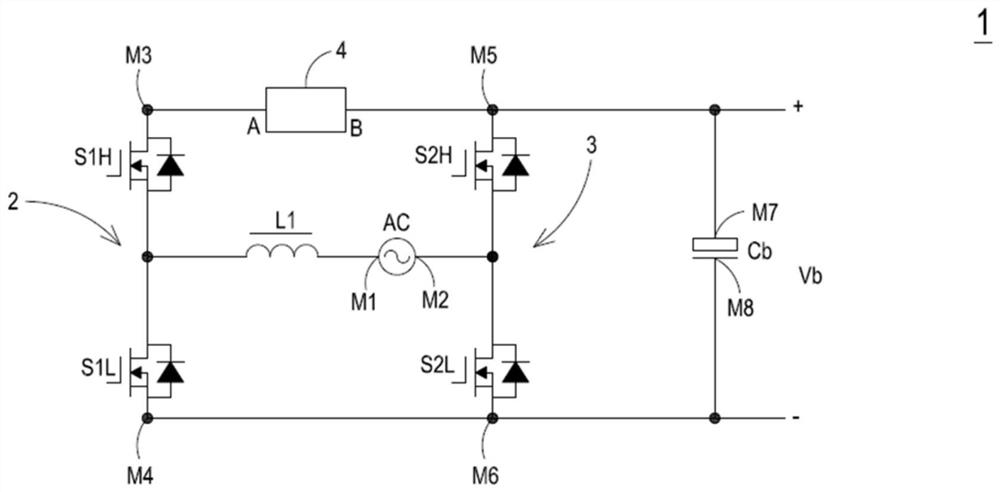
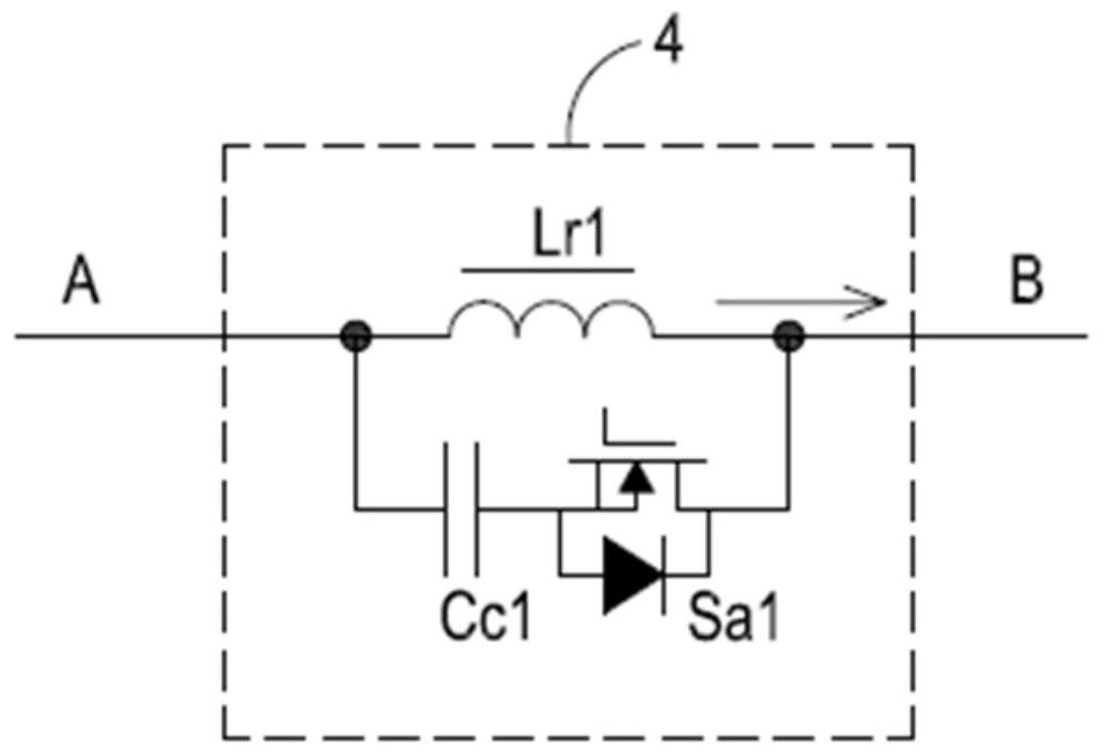
[0044] see figure 1 and figure 2 ,in figure 1 It is a schematic diagram of the circuit structure of the power factor correction circuit of the first embodiment of the present case, figure 2 for figure 1 A schematic diagram of the circuit structure of the first embodiment of the first active clamping unit of the power factor correction circuit shown. As shown in the figure, the power factor correction circuit 1 of this embodiment includes an input power source AC, a first bridge arm 2 , a first inductance element L1 , a second bridge arm 3 , an output capacitor Cb and a first active clamp unit 4 . The input power source AC outputs an AC input voltage to the power factor correction circuit 1, wherein the AC input voltage can be but not limited to a sine wave, and the input power source AC has a first terminal M1 and a second terminal M2. The first bridge arm 2 h...


PUM


Abstract

The invention discloses a power factor correction circuit which comprises an input power supply, a first bridge arm, a second bridge arm, an output capacitor and an active clamping unit. The first bridge arm has a first switching tube and a second switching tube connected in series with each other. The second bridge arm has a third switching tube and a fourth switching tube connected in series with each other. The active clamping unit comprises a second inductance element, a clamping capacitor and a fifth switching tube; therefore, the active clamping unit can be matched with the switching time sequence of the first switching tube, the second switching tube, the third switching tube and the fourth switching tube; therefore, soft switching of the first switching tube and the second switching tube of the power factor correction circuit is achieved, the switching loss of the first switching tube and the second switching tube in the first bridge arm is reduced, the working frequency of thepower factor correction circuit can be improved, and high power density and high efficiency are achieved.

Description

technical field [0001] The invention relates to the application field of switching power supplies of power electronics technology, in particular to a power factor correction circuit. Background technique [0002] At present, switching power supply products are improving towards high efficiency, high power density, high reliability and low cost, and power factor correction circuits in switching power supply products, such as totem pole power factor correction circuits, mostly use wide bandgap devices. For example, gallium nitride power devices or silicon carbide power devices are used to form switches. Since wide bandgap devices have faster switching speeds and lower switching losses, they can help switching power supply products improve efficiency while helping switching power supply products Improve operating frequency and power density. In addition, the equivalent parasitic diode in the wide bandgap device has lower reverse recovery characteristics, which makes the totem ...

Claims


Application Information

Patent Timeline
Patent Type & Authority Applications(China)
IPC IPC(8): H02M1/42
CPCH02M1/4233H02M1/0058Y02B70/10H02M1/342Y02P80/10H02M1/344H02M1/0003H02M1/34H02M1/4241H02M7/219
Inventor 徐德鸿董慨章进法
Owner ZHEJIANG UNIV
Why Eureka
Try Eureka