Coal mine underground ventilation structure convenient to fix

A technology for underground ventilation and coal mines, which is applied in mining equipment, mining equipment, earthwork drilling and mining, etc. It can solve the problems of inconvenient folding and transportation, poor overall stability of the structure, and height adjustment of ventilation pipes, etc., to achieve mutual storage and transportation. , easy to adjust the effect

Active Publication Date: 2020-11-03
府谷县谊丰煤矿有限公司
View PDF9 Cites 0 Cited by
  • Summary
  • Abstract
  • Description
  • Claims
  • Application Information

AI Technical Summary

Problems solved by technology

[0003] The purpose of the present invention is to provide a coal mine underground ventilation structure that is easy to fix. Through the setting of the sliding socket between the third rod body and the fourth rod body, it is convenient to adjust according to the height of the shaft, and it is convenient for the second fixing plate and the third fixing plate The fixed connection with the well wall, through the setting of the first rod body and the second rod body and the cooperation with the support rod, the device can be arranged in a triangle shape, which improves the stability of the device, and the disassembly of one end of the support rod is facilitated by the setting of the post , through the setting of the connecting rod, the relative rotation and storage between the second rod body and the third rod body can be realized, and the setting of the second limit bar and the third limit bar can be used to adjust the height of the ventilation pipe, which can be aimed at The rapid ventilation of different areas in the hoistway solves the problem of poor applicability of the existing downhole ventilation pipe fixing structure and inconvenient fixation with the hoistway wall, poor overall structure stability, inconvenient folding and transportation, and inability to adjust the height of the ventilation pipe question

Method used


Image

  • Coal mine underground ventilation structure convenient to fix
  • Coal mine underground ventilation structure convenient to fix
  • Coal mine underground ventilation structure convenient to fix

Examples


Embodiment 1

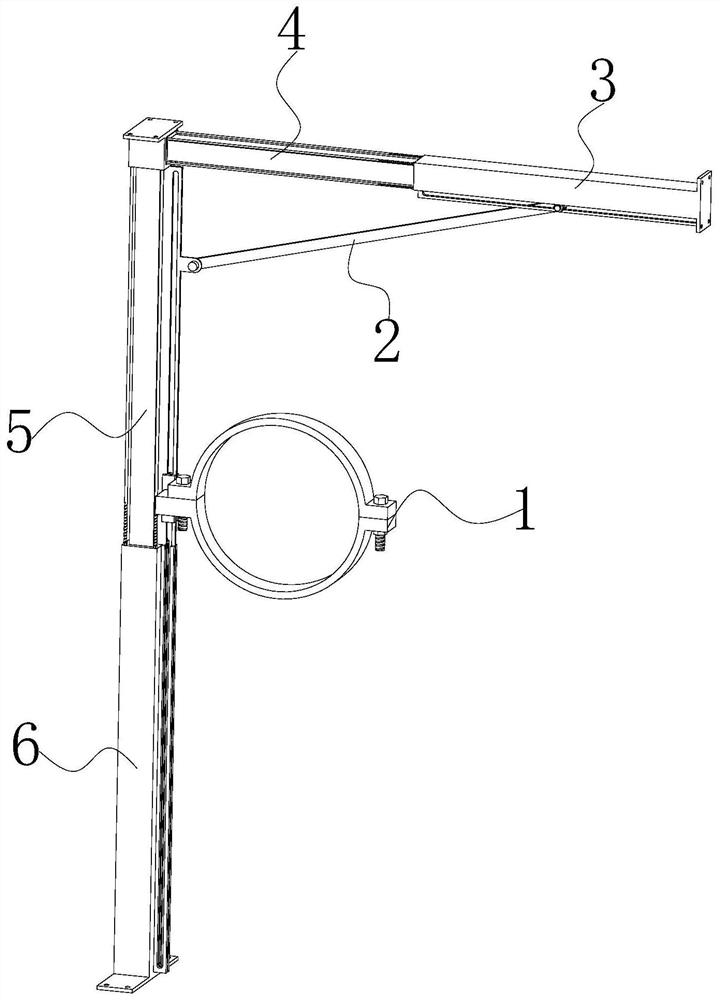
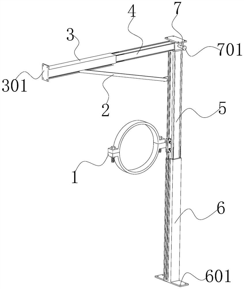
[0053] see Figure 1-2 As shown, the present invention is a coal mine underground ventilation structure that is convenient for fixing, including a first rod body 3, a second rod body 4, a third rod body 5 and a fourth rod body 6. As can be seen from the accompanying drawings, the above-mentioned components are all rectangular Set, one end of the second rod body 4 is slidingly sleeved in one end of the first rod body 3, this setting can be used to adjust the relative position adjustment between the first rod body 3 and the second rod body 4, and one end of the third rod body 5 is slidingly sleeved Connected to one end of the fourth rod body 6, the second rod body 4 is located at the upper end position of the third rod body 5 and is perpendicular to the third rod body 5; this setting can be used to adjust the relative relationship between the third rod body 5 and the fourth rod body 6. For position adjustment, the connecting body of the third rod body 5 and the fourth rod body 6...


PUM


Abstract

The invention discloses a coal mine underground ventilation structure convenient to fix, and relates to the technical field of coal mine ventilation. The coal mine underground ventilation structure comprises a first rod body, a second rod body, a third rod body and a fourth rod body; one end of the second rod body is slidably connected into one end of the first rod body in a sleeved manner, one end of the third rod body is slidably connected into one end of the fourth rod body in a sleeved manner, and the second rod body is located at the upper end of the third rod body and is perpendicular tothe third rod body; a clamp is further arranged on a connecting body of the third rod body and the fourth rod body in a matched manner; and first inserting grooves are formed in the four corners of the end face, close to the second rod body, of the first rod body. According to the coal mine underground ventilation structure, through the arrangement of a supporting rod, the first rod body, the second rod body, the third rod body, the fourth rod body, a second limiting strip, a third limiting strip, a first clamping plate, a second clamping plate, an inserting column and a connecting rod, the coal mine underground ventilation structure is convenient to install and high in safety in the using process, rapid and efficient ventilation can be achieved by the coal mine underground ventilation structure, and the coal mine underground ventilation structure is high in applicability; and meanwhile, the coal mine underground ventilation structure is good in folding and storage effect and convenient to transport.

Description

technical field [0001] The invention belongs to the technical field of coal mine ventilation, and in particular relates to a coal mine underground ventilation structure which is convenient for fixing, and is mainly used for fixing and installing underground ventilation pipes. Background technique [0002] Mine ventilation refers to entering fresh air into the mine to increase the oxygen concentration to dilute and remove toxic and harmful gases and dust in the mine. Harmful gas and dust, ensure safe production, adjust underground climate, and create a good working environment. The existing downhole ventilation pipe needs to be fixed and installed at a fixed distance through a fixed structure during the pipe arrangement process. At present, most of the structures used for fixing the downhole ventilation pipe are of fixed size, which cannot be adjusted according to the size of the shaft. Adjustment, poor applicability and inconvenient fixing with the well wall, secondly, the ...

Claims


Application Information

Patent Timeline
Patent Type & Authority Applications(China)
IPC IPC(8): E21F17/02
CPCE21F17/02
Inventor 曹芹
Owner 府谷县谊丰煤矿有限公司
Why Eureka
Try Eureka