Eureka AIR delivers breakthrough ideas for toughest innovation challenges, trusted by R&D personnel around the world.

Transmission rotating force elastic connector

An elastic connector and elastic connection technology, which is applied in the direction of elastic couplings, couplings, mechanical equipment, etc., can solve the problems of low cost of use, failure to connect the transmission rotating shaft, high cost performance, etc., and achieve low cost of use, transmission Powerful, cost-effective effect

Pending Publication Date: 2020-11-03
许巩固
View PDF0 Cites 0 Cited by
  • Summary
  • Abstract
  • Description
  • Claims
  • Application Information

AI Technical Summary

Problems solved by technology

[0005] The purpose of the present invention is to provide an elastic connector for transmission of rotational force, which can still maintain the rotational force of the counter-axis transmission and the elastic operation rotation with front and rear expansion and contraction in the case of coaxial error of the transmission rotation shafts on both sides in any precision machinery. It can effectively solve the problem that the transmission rotating shaft with position error cannot be connected, and can effectively make the transmission force stronger. It can also be connected to the transmission shaft of the vibrating machine, which can prevent the mechanical vibration from affecting the power rotation. Position error leads to vibration and fracture, which can avoid the problem of frequent maintenance of machinery and waste of time and labor. It is suitable for any climate and any mechanical shaft connection. The product is durable, cost-effective, and low in use cost to solve the above-mentioned background technology. proposed question

Method used


Image

  • Transmission rotating force elastic connector
  • Transmission rotating force elastic connector
  • Transmission rotating force elastic connector

Examples


Embodiment Construction

[0040] The following will clearly and completely describe the technical solutions in the embodiments of the present invention with reference to the accompanying drawings in the embodiments of the present invention. Obviously, the described embodiments are only some, not all, embodiments of the present invention. Based on the embodiments of the present invention, all other embodiments obtained by persons of ordinary skill in the art without making creative efforts belong to the protection scope of the present invention.

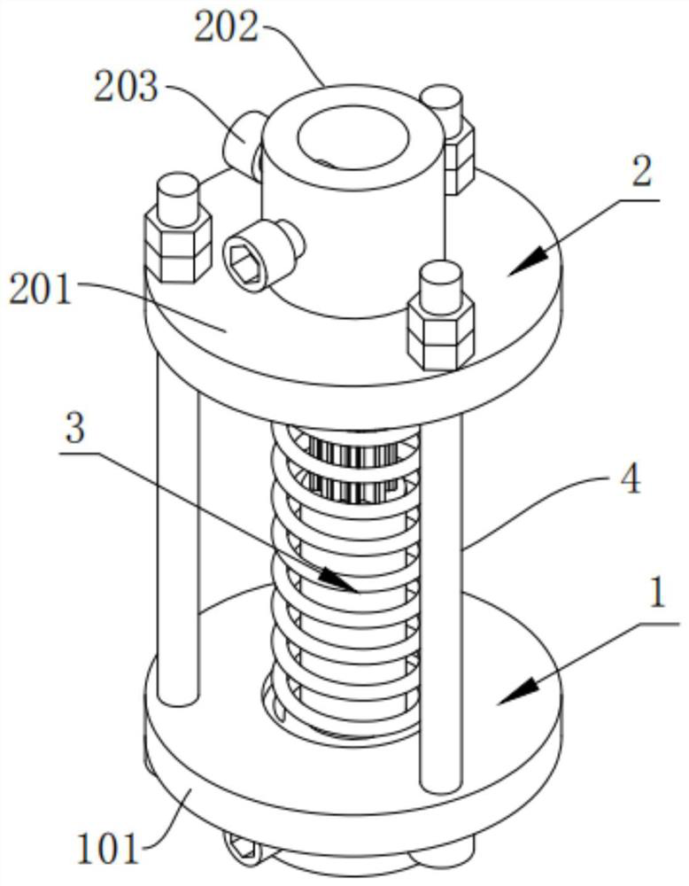
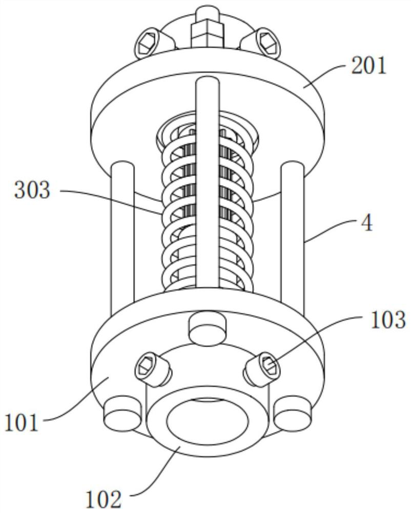
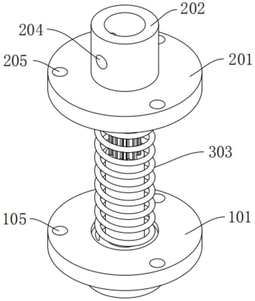
[0041] see Figure 1-7 , the present invention provides a technical solution:

[0042] An elastic connector for transmitting rotational force, comprising:

[0043] The first connection mechanism 1, the first connection mechanism 1 includes a first connection seat 101 and a first connection sleeve 102, the first connection sleeve 102 is fixedly installed on one side of the first connection seat 101, the Both the first connecting base 101 and the first connect...


PUM


Abstract

The invention discloses a transmission rotating force elastic connector. The transmission rotating force elastic connector comprises a first connecting mechanism, a second connecting mechanism and anelastic connecting mechanism, wherein the first connecting mechanism comprises a first connecting seat and a first connecting sleeve. The transmission rotating force elastic connector can still keep counter-shaft transmission rotating force and elastic operation rotation with a front-back extendable effect under the condition that coaxial errors exist in transmission rotating shafts on the two sides in any precision machine, can effectively solve the problem that the transmission rotating shafts with position errors cannot be in butt joint, further can effectively enable transmission force tobe stronger, can be connected with a transmission shaft of a vibration machine, can prevent mechanical vibration from influencing power rotation, has extendable elastic performance, and therefore cangreatly reduce the situation of vibration breakage caused by the position errors, can avoid the problem that time and labor are wasted due to frequent maintenance of the machine, and is suitable for shaft connection of any weather and any machine, durable in product, high in cost performance and low in use cost.

Description

technical field [0001] The invention relates to the technical field of transmission shaft connection, in particular to an elastic connector for transmission of rotational force. Background technique [0002] The transmission shaft is a rotating body with high speed and few bearings, so its dynamic balance is very important. Generally, the transmission shaft must undergo a dynamic balance test before leaving the factory and be adjusted on a balancing machine. The transmission rotating shaft is a kind of transmission shaft. The transmission rotary force connector is a connecting device that connects the drive shafts on both sides. [0003] However, when using the transmission rotation force connector in the prior art to connect the transmission shafts on both sides, there is a problem that the precision machinery cannot connect to the transmission rotation shaft when the position error occurs when the transmission shafts on both sides are connected in the past, so the mechan...

Claims


Application Information

Patent Timeline
IPC IPC(8): F16D3/72
CPCF16D3/72
Inventor 许巩固
Owner 许巩固
Why Eureka
Eureka Blog
Learn More