Current sensor

A current sensor, body technology, applied in the direction of only measuring current, measuring current/voltage, instruments, etc., can solve the problems of difficult installation, not moisture-proof, etc., and achieve the effect of stable installation

Pending Publication Date: 2020-11-03
SHANGHAI ZHIXIN INTELLIGENT ELECTRIC CO LTD +2
View PDF6 Cites 0 Cited by
  • Summary
  • Abstract
  • Description
  • Claims
  • Application Information

AI Technical Summary

Problems solved by technology

[0003] Aiming at the deficiencies of the prior art, the purpose of the present invention is to provide a current sensor to solve the problems in the prior art that are difficult to install and not moisture-proof

Method used


Image

  • Current sensor
  • Current sensor
  • Current sensor

Examples


Embodiment Construction

[0033] The embodiments of the present invention are described in detail below. This embodiment is implemented on the premise of the technical solution of the present invention, and detailed implementation methods and specific operating procedures are provided, but the protection scope of the present invention is not limited to the following implementation example.

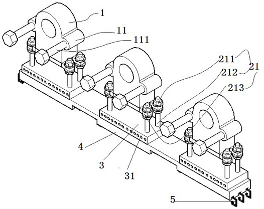
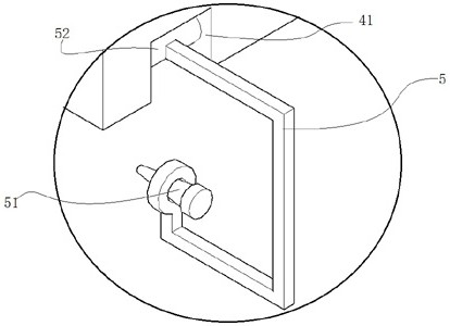
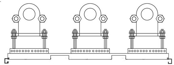
[0034] Such as Figure 1-4 As shown, a current sensor includes three current sensor bodies 1, and the three current sensor bodies 1 are respectively an A-phase current sensor body, a B-phase current sensor body, and a C-phase current sensor body, wherein the current sensor body 1 is an existing Conventional current sensors disclosed in the art.

[0035] In order to improve the installation stability of the current sensor body 1, which is suitable for complex installation and moisture-proof, the bottoms of the above-mentioned three current sensor bodies 1 are fixedly connected with a moisture-proof plate 3; the moi...


PUM


Abstract

The invention discloses a current sensor, which comprises three current sensor bodies and a moisture-proof plate, and is characterized in that the bottoms of the three current sensor bodies are fixedly connected to the moisture-proof plate; the bottom of the current sensor body is fixedly connected to the top of the moisture-proof plate through a plurality of height adjustment connecting pieces. The height adjusting connecting piece comprises a bulge arranged at the bevel part of the bottom of the current sensor body; the height adjusting connecting piece further comprises a screw rod penetrating through the protrusion. The screw rod is in threaded connection with two extrusion nuts which are matched with each other; the extrusion nuts respectively extrude the top and the bottom of the bulge; the current sensor body further comprises an installation part fixedly connected to the bottom of the moisture-proof plate. By adopting the above device parts, stable installation can be achieved,and the current sensor body can be effectively protected from being affected with damp through the design of the device parts.

Description

technical field [0001] The invention relates to the field of current sensor body devices, in particular to a current sensor. Background technique [0002] Current sensor is a relatively common current sensing and detection component. During the construction of electric power work, it is often necessary to assemble the current sensor body on the carrier such as the wall and other attachments, such as installed in the primary and secondary fusion ring main unit At this time, due to the fact that the primary and secondary fusion ring network cabinets are often installed outdoors and lack wind and rain shielding devices, dampness occurs in the ring network cabinets, especially at the bottom of the ring network cabinets that are in contact with the ground. The positioning structure on the current sensor body is relatively simple, and it can only be used to fix attachments of more conventional shapes. In the ring network cabinet, it does not have a good moisture-proof ability, and...

Claims


Application Information

Patent Timeline
Patent Type & Authority Applications(China)
IPC IPC(8): G01R19/00
CPCG01R19/0092
Inventor 李自清丁永生冯娟宋云翔李力邢峻包铁华杨佳泉孙育群姜富修杜丽
Owner SHANGHAI ZHIXIN INTELLIGENT ELECTRIC CO LTD
Why Eureka
Try Eureka