
Continuous forming device for powder metallurgy based on limiting transmission

A molding device and powder metallurgy technology, applied in the field of powder metallurgy, can solve problems such as shortening the service life of feeding plates and extrusion rods, low processing efficiency, and damage to circuit boards, so as to avoid repeated reciprocating movements, reduce production costs, and increase usage. The effect of longevity

Inactive Publication Date: 2020-11-06
南知周
View PDF0 Cites 0 Cited by
  • Summary
  • Abstract
  • Description
  • Claims
  • Application Information

AI Technical Summary

Problems solved by technology

[0003] However, traditional powder metallurgy press molding devices operate on a single mold. During the pressing process, the product is pressed and formed through the reciprocating intermittent motion of the feeding plate and the extrusion rod. The processing efficiency is low, and the feeding plate and extrusion rod The long-term reciprocating movement of the pressing rod is more likely to cause wear and shorten the service life of the feeding plate and the extrusion rod, and the regular intermittent movement of the feeding plate and the extrusion rod needs to be realized by programming, which is not only more expensive, but also in The circuit board is also prone to damage during use

Method used


Image

  • Continuous forming device for powder metallurgy based on limiting transmission
  • Continuous forming device for powder metallurgy based on limiting transmission
  • Continuous forming device for powder metallurgy based on limiting transmission

Examples


Embodiment Construction

[0023] The following will clearly and completely describe the technical solutions in the embodiments of the present invention with reference to the accompanying drawings in the embodiments of the present invention. Obviously, the described embodiments are only some, not all, embodiments of the present invention. Based on the embodiments of the present invention, all other embodiments obtained by persons of ordinary skill in the art without making creative efforts belong to the protection scope of the present invention.

[0024] The embodiment of the continuous molding device for powder metallurgy based on limit transmission is as follows:

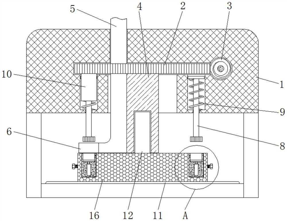
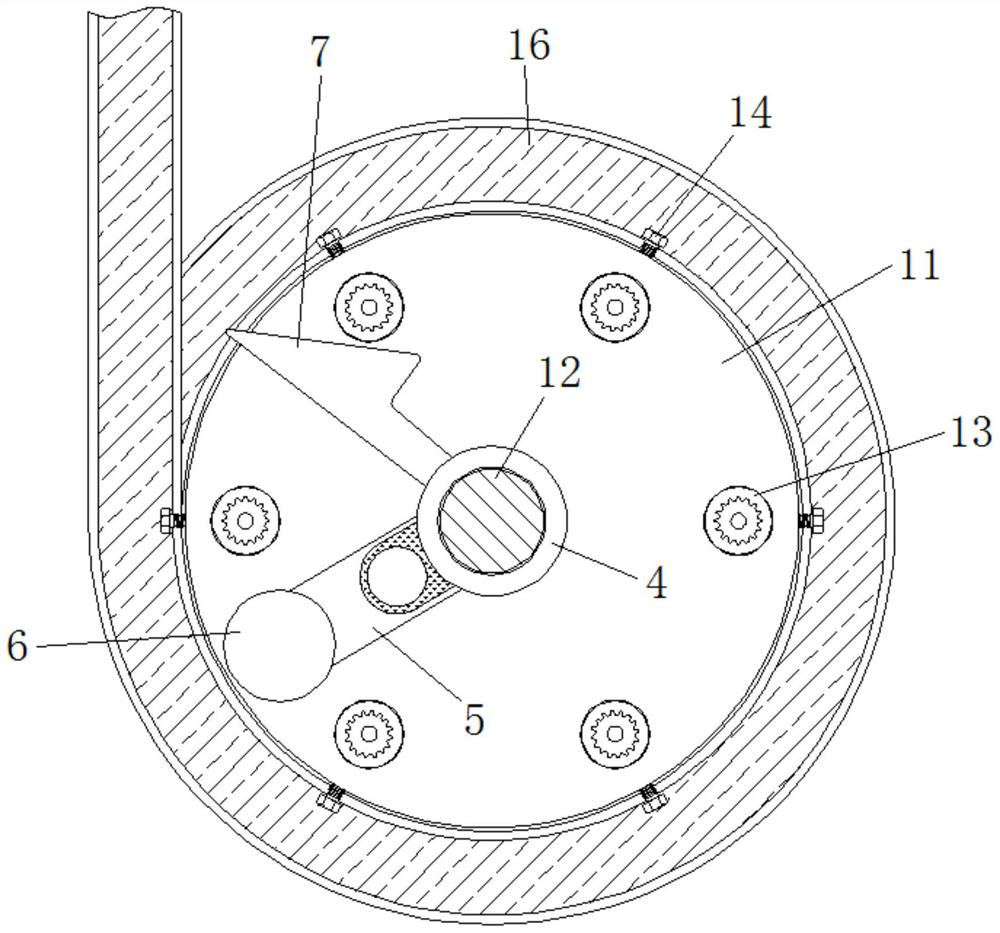
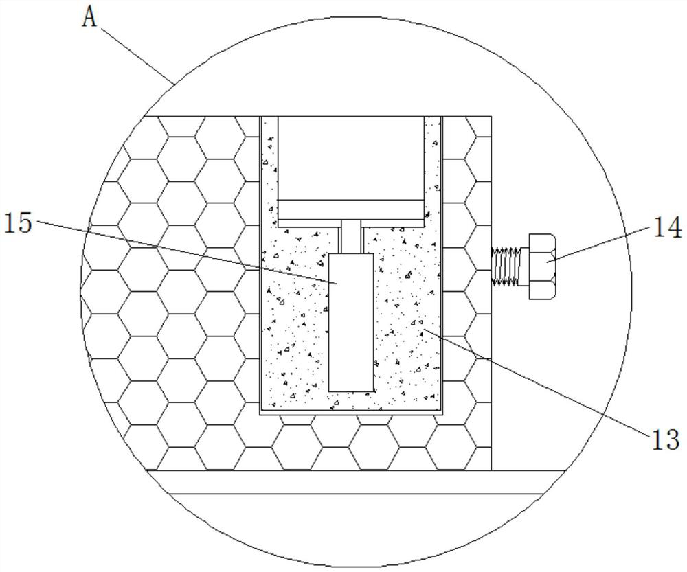
[0025] see Figure 1-5 , a continuous molding device for powder metallurgy based on limit transmission, including a frame body 1, a gear plate 2, a threaded rod 3, a sleeve 4, a feeding pipe 5, a feeding plate 6, a push plate 7, an extrusion rod 8, Spring 9, arc plate 10, base 11, column 12, mold 13, fastening bolt 14, hydraulic rod 15, co...


PUM


Abstract

The invention provides a continuous forming device for powder metallurgy based on limiting transmission, and relates to the technical field of powder metallurgy. The continuous forming device for powder metallurgy based on limiting transmission comprises a frame body, wherein a fluted disc is rotationally connected to the interior of the frame body, a threaded rod is rotationally connected to theright side of the fluted disc in the frame body, a sleeve is fixedly installed at the bottom end of the fluted disc, a conveying pipe is fixedly installed on the outer side of the sleeve, a feeding plate is fixedly installed at the bottom end of the conveying pipe, and a push plate is fixedly installed on the outer side of the sleeve. According to the continuous forming device for powder metallurgy based on limiting transmission, feeding and pressing of a mold and collection of finished products can be continuously realized, the machining efficiency of pressing forming is improved, the repeated reciprocating motion of a single feeding plate and an extrusion rod is avoided, the abrasion is reduced, the service life is prolonged, the use of a complex circuit board is avoided, the manufacturing cost is reduced, and damage is not prone to occurring.

Description

technical field [0001] The invention relates to the technical field of powder metallurgy, in particular to a continuous molding device for powder metallurgy based on limit transmission. Background technique [0002] Powder metallurgy is the process technology of producing metal powder or using metal powder as raw material, forming and sintering to manufacture metal materials, composite materials and various types of products. Powder metallurgy has similarities with the production of ceramics, and both belong to powder sintering technology. , due to the advantages of powder metallurgy technology, it has become the key to solve the problem of new materials, and plays a pivotal role in the development of new materials. [0003] However, traditional powder metallurgy press molding devices operate on a single mold. During the pressing process, the product is pressed and formed through the reciprocating intermittent motion of the feeding plate and the extrusion rod. The processing...

Claims


Application Information

Patent Timeline
Patent Type & Authority Applications(China)
IPC IPC(8): B22F3/00B22F3/03
CPCB22F3/005B22F3/03
Inventor 南知周
Owner 南知周
Learn More