An automatic loading and unloading device placed on the assembly line
An automatic loading and unloading and assembly line technology, applied in the direction of packaging, etc., can solve the problems of large amount of packing, laborious, slow, shovel can only be loaded with a small shovel at a time, and achieve the effect of preventing falling
- Summary
- Abstract
- Description
- Claims
- Application Information
AI Technical Summary
Problems solved by technology
Method used
Image
Examples
Embodiment 1
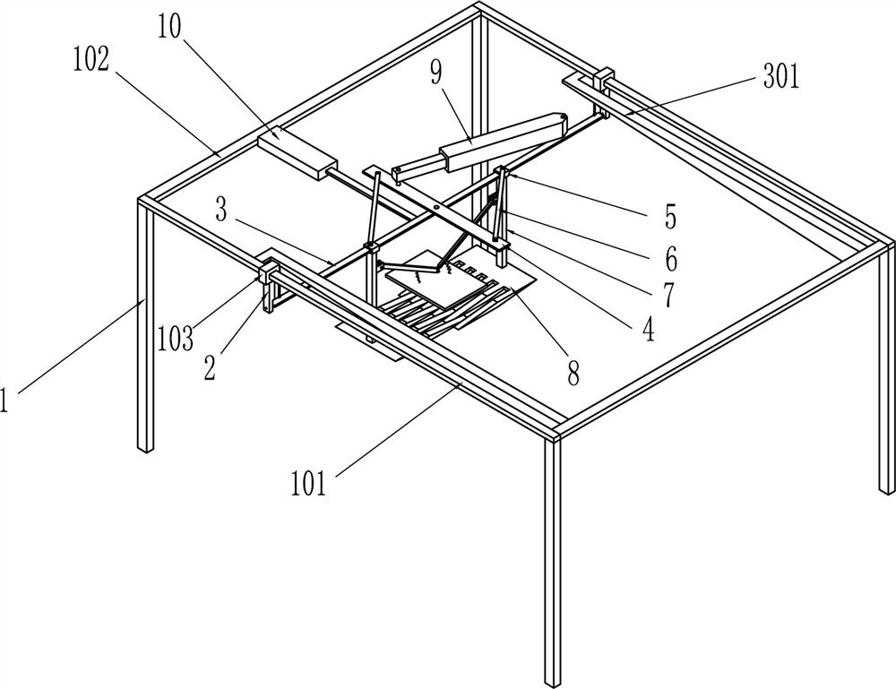
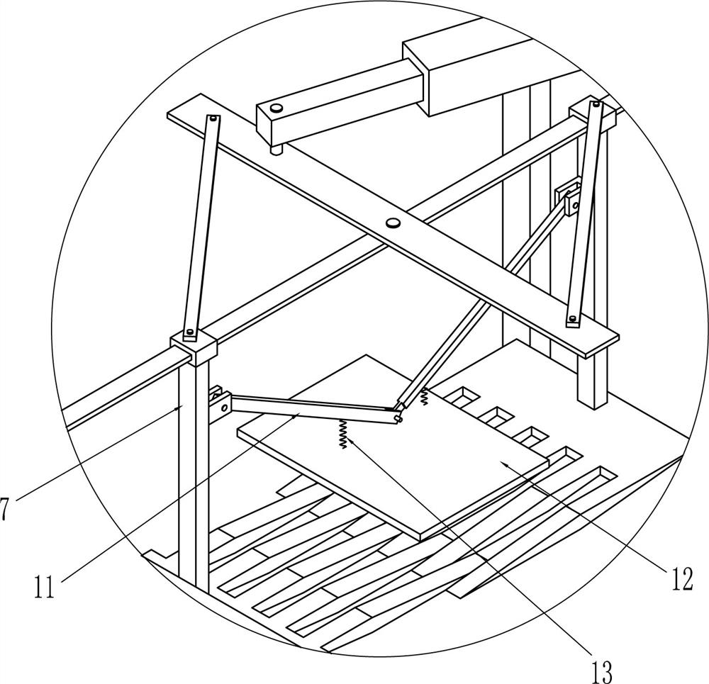
[0040] An automatic loading and unloading device placed on the assembly line, such as figure 1 As shown, it includes a support frame 1, a first guide sleeve 103, a swing seat 2, a turnover plate 3, a dumping mechanism, a horizontal plate 4, a second guide sleeve 5, a first connecting rod 6, a vertical support rod 7, and a shovel plate 8 , the cylinder 9 and the electric push rod 10, the two first guide sleeves 103 are respectively slidingly connected to the long poles 101 on the left and right sides of the support frame 1, and the two swing seats 2 are fixedly connected to the lower ends of the first guide sleeves 103 respectively, The two ends of the flap 3 are respectively connected to the swing seats 2 on both sides, the dumping mechanism is arranged on the support frame 1 and connected to the flap 3, the middle part of the horizontal plate 4 is hinged with the middle part of the flap 3, and the two second guide sleeves 5 slide Connected to the flap 3 and located on both si...
Embodiment 2
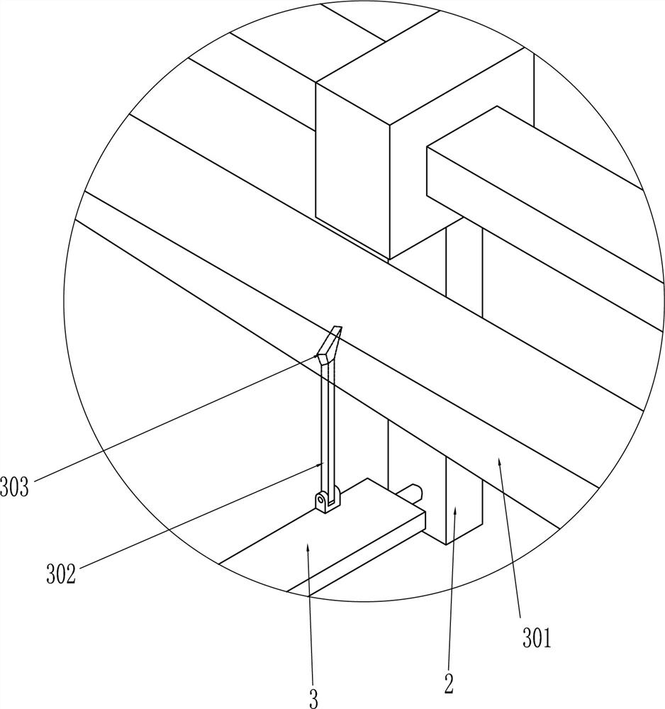
[0043] On the basis of Example 1, as Figure 1-3 As shown, the dumping mechanism includes a guide rail 301, a swing lever 302 and an inclined slider 303. The front end of the guide rail 301 is vertically fixed to the front side short pole 102 of the support frame 1, and the rear end of the guide rail 301 is fixed. Connected to the long support rod 101, the guide rails 301 on both sides are symmetrical, and the two swing rods 302 are respectively connected to the left and right sides of the top of the flap 3 in rotation, and the inclined slider 303 is fixed on the top of the swing rod 302. The guide rail 301 is slidably connected.
[0044] When the turning plate 3 moved forward, the swing lever 302 hinged with the turning plate 3 moved in the track of the guide rail 301 by the inclined slider 303, because the guide rail 301 was an inclined track, so when the inclined slider 303 moved forward The swing bar 302 drives the turnover plate 3 to tilt, and realizes the function of au...
PUM
 Abstract
Description
Claims
Application Information
 - R&D
- Intellectual Property
- Life Sciences
- Materials
- Tech Scout
- Unparalleled Data Quality
- Higher Quality Content
- 60% Fewer Hallucinations
Browse by: Latest US Patents, China's latest patents, Technical Efficacy Thesaurus, Application Domain, Technology Topic, Popular Technical Reports.
© 2025 PatSnap. All rights reserved.Legal|Privacy policy|Modern Slavery Act Transparency Statement|Sitemap|About US| Contact US: help@patsnap.com


