
An optical path delay encoding method and encoding system

A technology of time-delay coding and optical path, which is applied in the direction of instruments, etc., can solve the problems of insufficient application of counting pulse time-related information, inability to identify useful signals and noise signals, and unoptimized detection results, etc., to achieve simple structure and improved Anti-noise performance, the effect of simple coding

Active Publication Date: 2021-11-09
SICHUAN JIUZHOU ELECTRIC GROUP
View PDF7 Cites 0 Cited by
  • Summary
  • Abstract
  • Description
  • Claims
  • Application Information

AI Technical Summary

Problems solved by technology

However, single-photon detectors have many technical limitations in lidar and communication applications, including general single-photon detectors, in order to achieve single-photon level sensitivity, high gain but limited dynamic range, and the detection of light usually only outputs a representation The standard photon counting pulse with two states of photons "present" or "absent" cannot distinguish the number of arriving photons, that is, the light intensity, nor can it use the intensity of the output signal to identify useful signals and noise signals in one detection
[0003] In order to solve this defect, at present, the time correlation of counting pulses is generally used to directly accumulate the coincidence counting results of single photon pulses. By accumulating a sufficient number of photon counting pulses, a high-contrast photon counting distribution can be obtained to distinguish noise. However, , the coincidence counting method only uses the intensity information obtained by accumulating multiple counting pulses, but the time-related information of the counting pulses is not fully used, and its detection effect is not optimal, resulting in a waste of information resources

Method used


Image

  • An optical path delay encoding method and encoding system
  • An optical path delay encoding method and encoding system
  • An optical path delay encoding method and encoding system

Examples


Embodiment

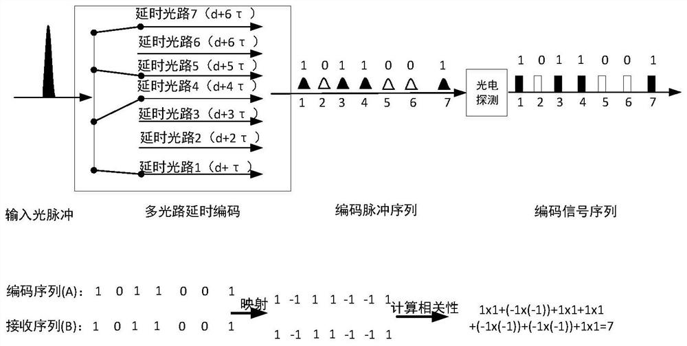
[0037] Such as figure 1 As shown, an optical path delay coding method includes the following steps:

[0038] Obtain one or more beams of optical pulse signals, and input the optical pulse signals to the optical path delay coding system to obtain a coded delayed optical pulse sequence;

[0039] The delayed light pulse sequence is sequentially input to the single-photon detector, and the single-photon detector detects the delayed light pulse sequence to obtain a corresponding counting pulse signal sequence;

[0040] According to the coding structure in the counting pulse signal sequence, the obtained counting pulse sequence is decoded to improve the signal-to-noise ratio of the received signal.

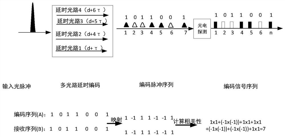
[0041] Specifically, in this embodiment, the optical path delay encoding system includes two forms: (1) The optical path delay encoding system includes an optical receiving end, a beam splitter, and a first delay channel. This kind of optical path delay encoding system is used when th...


PUM


Abstract

The invention discloses an optical path delay encoding method and encoding system. The method includes the following steps: acquiring one or more beams of optical pulse signals, and inputting the optical pulse signals into the optical path delay encoding system to obtain a delay Optical pulse sequence; input the delayed optical pulse sequence to a single photon detector in sequence, and the single photon detector performs photon counting detection on the delayed optical pulse sequence to obtain a corresponding counting pulse signal sequence; according to the counting pulse The encoding structure in the signal sequence decodes the count pulse signal sequence. The object of the present invention is to provide an optical path delay encoding method and system, through which the anti-noise performance of the receiving system can be improved, and the time-domain loss caused by the encoding method at the transmitting end in the laser radar detection can be made up. Waste problem, and the encoding system has a simple structure, low implementation cost, high application value, and good operability.

Description

technical field [0001] The invention relates to the field of laser radar detection and coding technology, in particular to an optical path delay coding method and coding system. Background technique [0002] Single-photon detector (SPD, single-photon detector) is a high-sensitivity single-photon detector that can respond to photon-level signals. Detectors are the basis of single-photon radar detection, quantum communication and other fields. However, single-photon detectors have many technical limitations in lidar and communication applications, including general single-photon detectors, in order to achieve single-photon level sensitivity, high gain but limited dynamic range, and the detection of light usually only outputs a representation The standard photon counting pulse with two states of photons "present" or "absent" cannot distinguish the number of arriving photons, that is, the light intensity, nor can it use the intensity of the output signal to identify useful sign...

Claims


Application Information

Patent Timeline
Patent Type & Authority Patents(China)
IPC IPC(8): G01J11/00
CPCG01J11/00
Inventor 杨林祝月兵任瑞刘江冯波叶鹏
Owner SICHUAN JIUZHOU ELECTRIC GROUP
Learn More