
Central air intake diversion structure and central air intake vacuum cyclone cleaner

A technology of placement and airflow, which is applied in the field of mid-mounted air intake guide structure, to achieve the effects of reducing volume and weight, reducing motor load, and reducing airflow resistance

Active Publication Date: 2022-03-29
张正干
View PDF5 Cites 0 Cited by
  • Summary
  • Abstract
  • Description
  • Claims
  • Application Information

AI Technical Summary

Problems solved by technology

[0005] In view of the above-mentioned problems in the prior art, one of the objectives of the present invention is to provide a central air intake guide structure and a central air intake vacuum cyclone cleaner including the intermediate air intake guide structure to solve the existing problems. Various limitations of vacuum cleaners

Method used


Image

  • Central air intake diversion structure and central air intake vacuum cyclone cleaner
  • Central air intake diversion structure and central air intake vacuum cyclone cleaner
  • Central air intake diversion structure and central air intake vacuum cyclone cleaner

Examples


Embodiment Construction

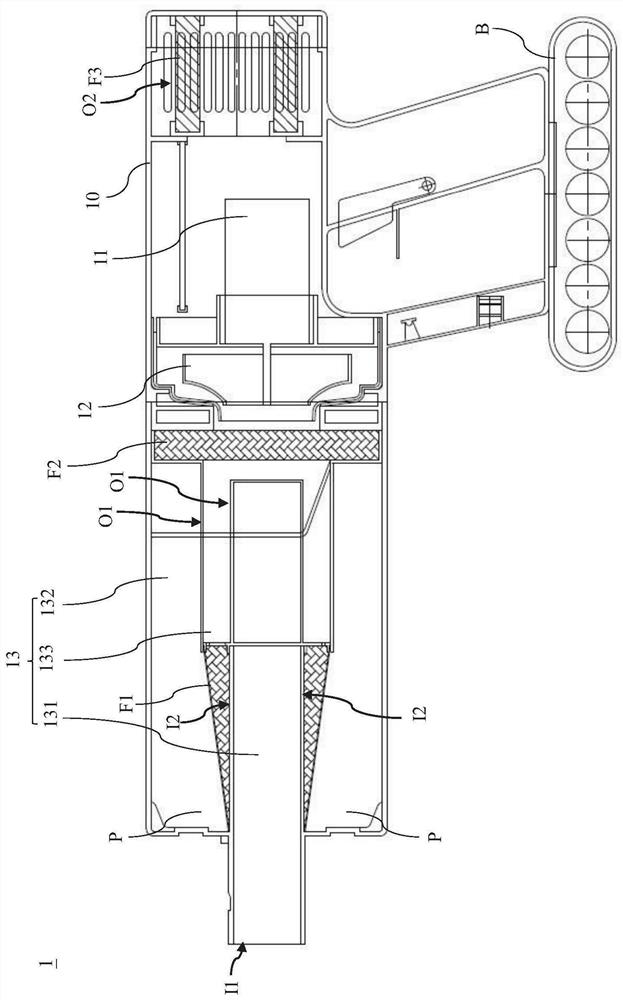
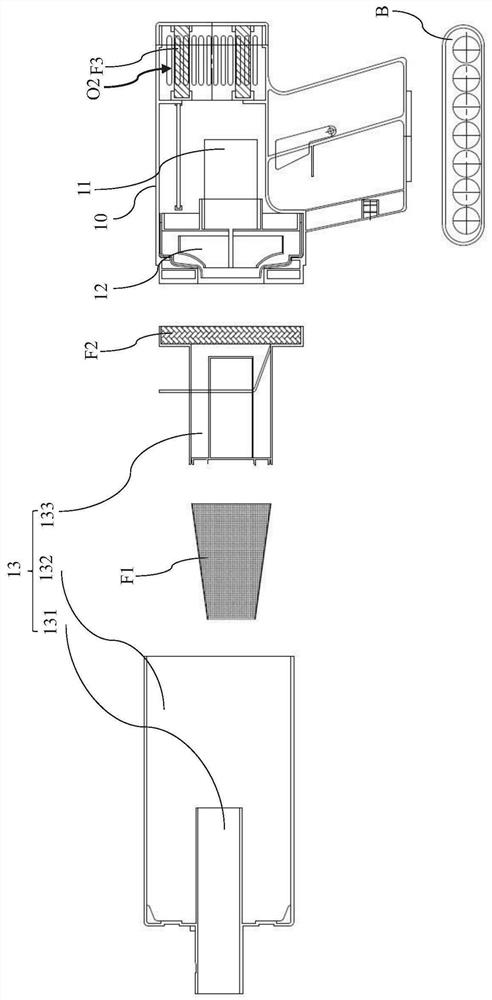
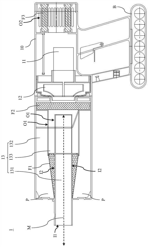
[0028] The following will refer to the relevant drawings to illustrate the embodiment of the mid-mounted air intake guide structure and the mid-mounted intake vacuum cyclone cleaner including the guide structure according to the present invention. For the sake of clarity and convenience in the description of the drawings, Each component may be presented exaggerated or reduced in size and proportion. In the following description and / or claims, when it is mentioned that an element is "connected" or "coupled" to another element, it may be directly connected or coupled to the other element or there may be an intervening element; When "directly connected" or "directly coupled" to another element, there are no intervening elements present, and other words used to describe the relationship between elements or layers should be interpreted in the same manner. For ease of understanding, the same components in the following embodiments are described with the same symbols.

[0029] see ...


PUM


Abstract

The invention provides a vacuum cyclone cleaner with a central air intake, which includes a central air intake guide structure. The central air intake guide structure includes a central air intake pipe, a centrifugal outer pipe and an exhaust inner pipe. The central air intake pipe includes a first air intake port and a first exhaust port. The central intake pipe is connected with the centrifugal outer pipe through the first exhaust port. The exhaust inner pipe includes a second air inlet, and the centrifugal outer pipe is connected with the exhaust inner pipe through the second air inlet. Wherein, the centrifugal outer pipe wraps the exhaust inner pipe, and the exhaust inner pipe wraps the central intake pipe.

Description

technical field [0001] The invention relates to a mid-mounted air intake guide structure, in particular to a mid-mounted intake air guide structure with small volume and simple structure. The invention also relates to a central air intake vacuum cyclone cleaner comprising the flow guiding structure. Background technique [0002] Vacuum cleaners are indispensable electrical appliances for every household; currently, vacuum cleaners on the market are mainly cyclone-separated. However, most of the current cyclone-separated vacuum cleaners adopt the design of the closed independent capsule centrifugal dust bucket, and the structural design of the closed independent capsule centrifugal dust bucket is to set an independent air inlet hose port on the outside of the closed independent capsule centrifugal dust bucket, and extend To the upper aperture of the independent capsule centrifugal dust bucket. In addition, there is a side suction aperture outside the independent capsule cen...

Claims


Application Information

Patent Timeline
Patent Type & Authority Patents(China)
IPC IPC(8): A47L5/24A47L9/16
CPCA47L5/24A47L9/16A47L9/1666A47L9/1683A47L9/165
Inventor 张正乾
Owner 张正干
Learn More