
Differential device capable of conveniently adjusting material width and cutting layer depth

A differential device and material technology, which is applied in feeding devices, automatic control devices, large fixed members, etc., can solve the problems of high cost of die cutting and high processing requirements of die cutting

Pending Publication Date: 2020-11-10
SUZHOU ANJIE TECH
View PDF7 Cites 0 Cited by
  • Summary
  • Abstract
  • Description
  • Claims
  • Application Information

AI Technical Summary

Problems solved by technology

[0002] In the die-cutting industry, when the material is cut and trimmed with a roller knife machine or a composite slitting machine, a layer of material tape is required under the material for support, and the cost of the cutting die is also relatively high; when the material needs to be cut in the thickness direction When cutting in half, the processing requirements for the cutting die are relatively high, and the cost of the cutting die is high, so a relatively low-cost differential device is urgently needed

Method used


Image

  • Differential device capable of conveniently adjusting material width and cutting layer depth
  • Differential device capable of conveniently adjusting material width and cutting layer depth
  • Differential device capable of conveniently adjusting material width and cutting layer depth

Examples


Embodiment Construction

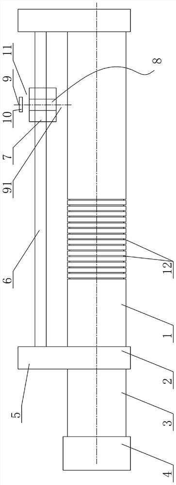
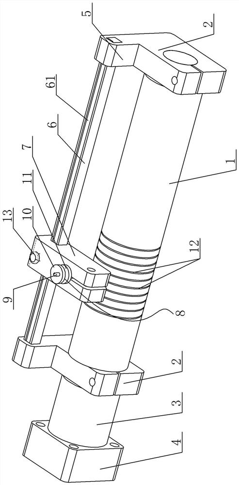
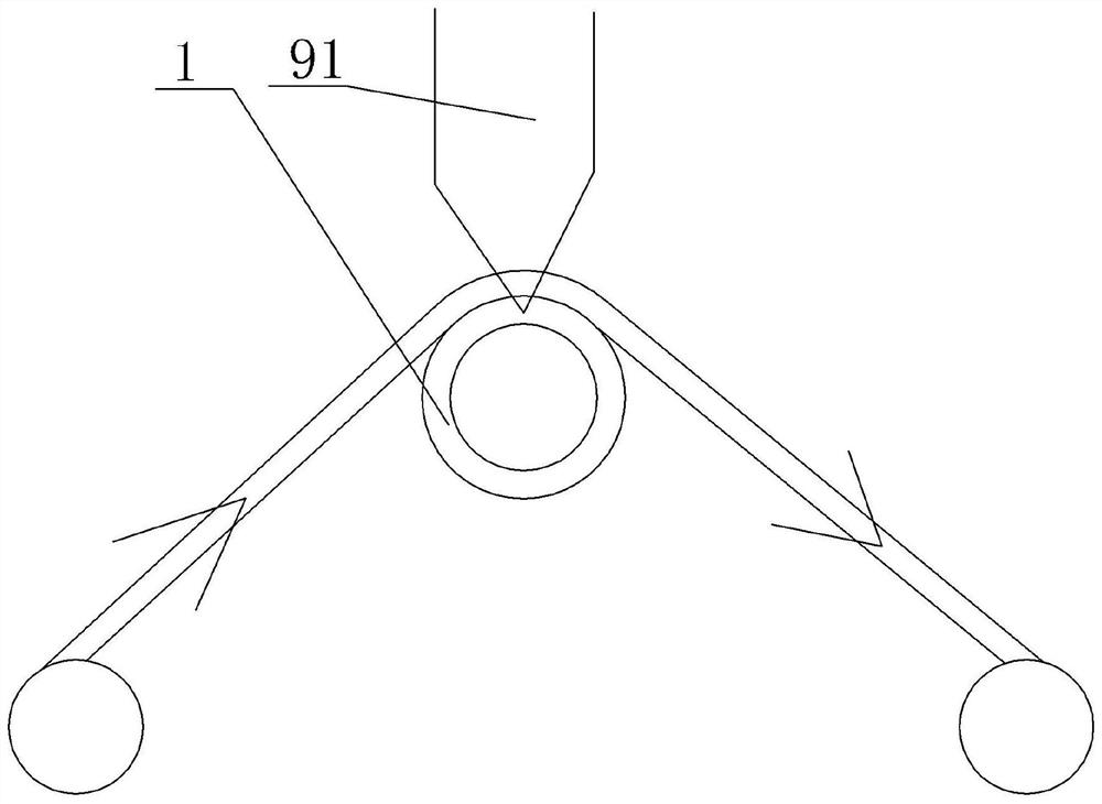
[0018] A differential device for convenient adjustment of material width and depth of cut, see Figure 1-Figure 4 : It includes a bottom shaft 1, the two ends of the length direction of the bottom shaft 1 are respectively inserted into the positioning holes of the corresponding mounting seat plate 2, the bottom shaft 1 is rotated relative to the mounting seat plate 2, and the outer side of the mounting seat plate 2 at one end is fixed A connection seat 3 is provided, the outer end of the connection seat 3 is provided with a connection positioning block 4, the connection positioning block 4 is used to be fixed on the machine, the top of the installation seat plate 2 protrudes to form a support frame 5, and the two sides of the transverse connecting rod 6 The end is inserted in the corresponding positioning hole of the support frame 5 at both ends, the transverse connecting rod 6 is provided with a cutter head fixing bracket 7, and the cutter head fixing bracket 7 is inserted wit...


PUM


Abstract

The invention provides a differential device capable of conveniently adjusting material width and cutting layer depth. The differential device can adjust the width and depth of a cut material according to actual needs, and is simple in structure, low in cost and good in universality. The two ends of a bottom shaft in the length direction are inserted into positioning holes of corresponding mounting seat plates correspondingly. The bottom shaft is rotationally arranged relative to the mounting seat plates. A connecting seat is fixedly arranged on the outer side of the mounting seat plate at oneend. A connecting positioning block is arranged at the outer end of the connecting seat and used for being fixedly connected to a machine. The tops of the mounting seat plates protrude upwards to form bearing frames. The two ends of a transverse connecting rod are inserted into corresponding positioning holes of the bearing frames at the two ends. The transverse connecting rod is sleeved with a tool bit fixing support. A tool bit is inserted into the position, corresponding to the position above the bottom shaft, of the tool bit fixing support. A tool bar is inserted into the axial center ofthe tool bit. A cutting edge is arranged at the bottom of the tool bar. An adjusting screw and a locking screw are arranged on the upper portion of the tool bar.

Description

technical field [0001] The invention relates to the technical field of die-cutting structures, in particular to a differential device for conveniently adjusting material width and cutting layer depth. Background technique [0002] In the die-cutting industry, when the material is cut and trimmed with a roller knife machine or a compound slitting machine, a layer of material belt is required under the material for support, and the cost of the cutting die is also relatively high; when the material needs to be cut in the thickness direction When cutting in half, the processing requirements for the cutting die are relatively high, and the cost of the cutting die is high, so a relatively low-cost differential device is urgently needed. Contents of the invention [0003] In view of the above problems, the present invention provides a differential device for conveniently adjusting the width and depth of the cut material, which can adjust the width and depth of the cut material ac...

Claims


Application Information

Patent Timeline
Patent Type & Authority Applications(China)
IPC IPC(8): B23Q1/25B23Q15/22
CPCB23Q1/25B23Q15/22B23Q15/225
Inventor 王春生叶寒石建平王永峰
Owner SUZHOU ANJIE TECH
Learn More