
A Dynamic Description Method for High Water Consumption Strips in Water Drive Reservoirs

A technology of water flooding oil and water consumption, which is applied in earthwork drilling, measurement, wellbore/well components, etc. It can solve the problems that cannot fully consider the particularity of high water consumption strips, long test time, limited and limited analysis, etc. , to achieve the effect of improving the development effect

Active Publication Date: 2021-06-25
CHINA UNIV OF PETROLEUM (EAST CHINA)
View PDF7 Cites 0 Cited by
  • Summary
  • Abstract
  • Description
  • Claims
  • Application Information

AI Technical Summary

Problems solved by technology

[0003] At present, there are very few studies on the description of high water consumption strips. The water absorption profile method and pressure drop curve method are mainly used to judge the existence of high water consumption strips, while the tracer test method and interference well test method place too much emphasis on the absolute value of the reservoir. Permeability, the results obtained only reflect the average properties of the reservoir, not the parameters of high water consumption strips, and these methods take a long time to test and are difficult to interpret
None of the above description methods for high water consumption strips can fully consider the particularity of high water consumption strips, and are often limited to qualitative analysis. At present, there is no effective description method for high water consumption strips

Method used


Image

  • A Dynamic Description Method for High Water Consumption Strips in Water Drive Reservoirs
  • A Dynamic Description Method for High Water Consumption Strips in Water Drive Reservoirs
  • A Dynamic Description Method for High Water Consumption Strips in Water Drive Reservoirs

Examples


Embodiment Construction

[0029] The present invention will be further described below in conjunction with the accompanying drawings and specific embodiments, so that those skilled in the art can better understand the present invention and implement it, but the examples given are not intended to limit the present invention.

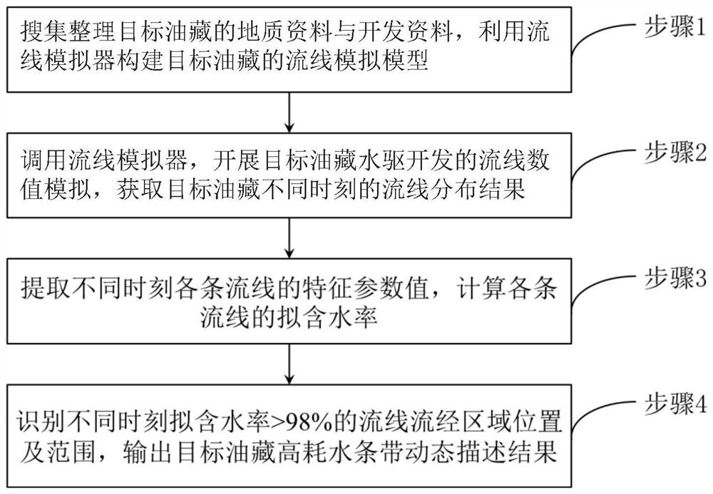
[0030] Such as figure 1 As shown, a dynamic description method for high water consumption strips in water flooding reservoirs includes the following steps:

[0031] Step 1. Collect and sort out the geological data and development data of the target reservoir, and use the streamline simulator to construct the streamline simulation model of the target reservoir.

[0032] The geological data include reservoir structure parameters, reservoir physical parameters and fluid physical parameters; the reservoir structure parameters include top structure and fault data; the reservoir physical parameters include formation pressure, formation temperature, oil layer thickness, oil saturation d...


PUM


Abstract

The invention relates to the technical field of oil and gas field development, and specifically discloses a dynamic description method for high water consumption strips in water drive oil reservoirs. It includes the following steps: Step 1, collect and organize the geological data and development data of the target reservoir, and use the streamline simulator to construct the streamline simulation model of the target reservoir; Step 2, call the streamline simulator to carry out water flooding of the target reservoir The developed streamline numerical simulation obtains the streamline distribution results of the target reservoir at different times; step 3, extracts the characteristic parameter values ​​of each streamline at different times, and calculates the pseudo water cut of each streamline; step 4, identifies the The position and range of the streamlines with pseudo water cut >98% flow through the area, and the dynamic description result of the high water consumption zone of the target reservoir is output. The present invention can more accurately realize the dynamic description of the development position, shape and range of each high water consumption strip in the water flooding reservoir by quickly identifying the position and range of the area where the streamline with the pseudo water content >98% flows through at different times, Provide guidance for improving the development effect of water flooding reservoirs.

Description

technical field [0001] The invention relates to the technical field of oil and gas field development, in particular to the technical field of high water consumption strips in water drive reservoirs. Background technique [0002] The high water consumption strip refers to the connected area formed during the long-term water flooding process with low oil saturation, the displacement factor is much larger than other areas, and does not have the potential for continuous water flooding. Oilfield development enters the late stage of ultra-high water cut. Affected by reservoir heterogeneity, high water consumption bands generally develop, resulting in inefficient and ineffective circulation of a large amount of injected water. Identifying and describing the high water consumption zone is the prerequisite for its effective treatment, and it is also of great significance for improving the development effect of ultra-high water-cut reservoirs and reducing production costs. [0003] A...

Claims


Application Information

Patent Timeline
Patent Type & Authority Patents(China)
IPC IPC(8): E21B47/00E21B49/00E21B43/20
CPCE21B43/20E21B47/00E21B49/00
Inventor 张先敏冯其红李闪闪晁政谢泽豪
Owner CHINA UNIV OF PETROLEUM (EAST CHINA)
Learn More