Hydraulic support safety valve working state monitoring method
A working state, hydraulic support column technology, applied in the direction of mine roof support, support/support, earthwork drilling, etc., can solve the problem of time-consuming and laborious, unable to reflect the opening pressure and opening time of safety valve, safety valve monitoring and other problems
Active Publication Date: 2020-11-10
CCTEG COAL MINING RES INST +1
5 Cites 3 Cited by
AI-Extracted Technical Summary
Problems solved by technology
[0005] In view of this, this application provides a monitoring method for the working state of the hydraulic support safety valve. The main purpose is to solve the problem that the existing hydraulic support safety valve needs to use a special monit...
Method used
Correspondingly, the cracking pressure standard value and the opening duration standard value of hydraulic support column safety valve are set, so that the actual cracking pressure and/or the opening pressure standard value and/or the opening duration standard value and hydraulic support column safety valve Compare the actual openin...
Abstract
The invention discloses a hydraulic support safety valve working state monitoring method, and relates to the technical field of coal mine safety mining. The method comprises the steps of obtaining thepressure change data of a hydraulic support stand column through the real-time monitoring of the pressure state of a coal mine working face hydraulic support stand column; and determining the workingstate of a coal mine working face hydraulic support stand column safety valve according to the pressure change data of the hydraulic support stand column and the working characteristics of the hydraulic support stand column safety valve. According to the technical scheme, the pressure of a coal mine working face hydraulic support is monitored in real time, the working resistance change conditionof the hydraulic support can be comprehensively obtained, and the opening pressure and duration of the coal mine working face hydraulic support safety valve are obtained according to the working stateof the safety valve; and therefore, the purposes of evaluating the working performance of the hydraulic support, roof weighting state and whether the safety valve is damaged or not are achieved.
Application Domain
Mining devicesMine roof supports +1
Technology Topic
Process engineeringCoal +6
Image
Examples
- Experimental program(1)
Example Embodiment
[0018] Hereinafter, exemplary embodiments of the present disclosure will be described in more detail with reference to the accompanying drawings. Although exemplary embodiments of the present disclosure are shown in the drawings, it should be understood that the present disclosure can be implemented in various forms and should not be limited by the embodiments set forth herein. On the contrary, these embodiments are provided to enable a more thorough understanding of the present disclosure, and to fully convey the scope of the present disclosure to those skilled in the art.
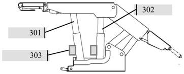
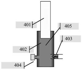
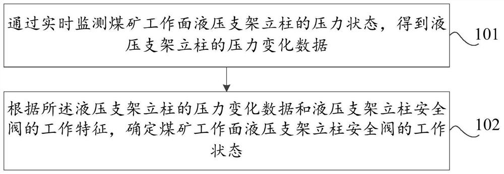
[0019] Aiming at the problem that there is no effective technical means to monitor the opening state of the safety valve in the well. This embodiment provides a method for monitoring the working status of the hydraulic support safety valve, which can monitor the pressure change data of the hydraulic support column in the coal mine, and combine the working characteristics of the hydraulic support column safety valve to determine the safety valve of the hydraulic support column at the coal mine face Working status, so as to further determine the actual opening pressure and opening duration of the safety valve in working status, and accurately reflect the actual working conditions of the safety valve in underground coal mine work. Such as figure 1 As shown, the method includes:
[0020] Step 101: Obtain pressure change data of the hydraulic support column by real-time monitoring of the pressure state of the hydraulic support column at the coal mining face.
[0021] In this embodiment, in the coal mining face, the pressure sensor is used to monitor the pressure of the hydraulic support column in real time, and the monitored pressure data is transmitted to the ground pressure monitoring system in real time through the optical cable or cable to achieve the Real-time monitoring of pressure changes of hydraulic supports. In addition, according to the pressure change data of the hydraulic support column, the working resistance change of the hydraulic support can be fully obtained, and combined with the working characteristics of the safety valve, the working status of the safety valve of the hydraulic support at the coal mining face and the safety valve's working status can be determined. Actual opening pressure and opening time.
[0022] Step 102: According to the pressure change data of the hydraulic support column and the working characteristics of the hydraulic support column safety valve, determine the working state of the hydraulic support column safety valve of the coal mine face.
[0023] In this embodiment, according to the pressure change data of the hydraulic support column and the working characteristics of the safety valve, the working state of the safety valve, as well as the actual opening pressure and opening time of the safety valve in the working state are automatically identified, so as to evaluate the work of the hydraulic support Performance, top pressure state, and whether the safety valve is damaged.
[0024] By applying the technical solution of this embodiment, compared with the existing solution where the safety valve of the hydraulic support needs to use a dedicated monitoring system to monitor the opening pressure on the ground, this embodiment monitors the pressure state of the hydraulic support column on the coal mining face in real time to obtain the hydraulic pressure The pressure change data of the support column; according to the pressure change data of the hydraulic support column and the working characteristics of the hydraulic support column safety valve, the working state of the hydraulic support column safety valve of the coal mining face is determined. It can be seen that this application can monitor the pressure change data of the hydraulic support column in the coal mine, and combine the working characteristics of the hydraulic support column safety valve to determine the working state of the hydraulic support column safety valve in the coal mine face, thereby further determining the safety valve in the working state The actual opening pressure and opening duration accurately reflect the actual working conditions of safety valves in underground coal mines.
[0025] Further, as a refinement and expansion of the specific implementation of the above embodiment, in order to fully explain the specific implementation process of this embodiment, another method for monitoring the opening state of the safety valve of a hydraulic support is provided, such as figure 2 As shown, the method includes:
[0026] Step 201: Obtain pressure change data of the hydraulic support column by real-time monitoring of the pressure state of the hydraulic support column at the coal mining face.
[0027] In specific implementations, sensors are used to monitor the pressure state of the emulsion in the hydraulic support column in real time, and according to the pressure state of the emulsion, the pressure change data of the hydraulic support column within a preset time is obtained. Such as image 3 , 4 As shown, the hydraulic support includes a support front column 301, a support rear column 302, and a sensor 303 (for example, a pressure sensor) arranged on the outer cylinder side of the column to monitor the pressure of the emulsion in the column. Further, the column is mainly composed of a rod body 401, The outer cylinder 402, the safety valve 403, the sensor 404, etc. are constituted, and the emulsion 405 is installed in the column. According to the needs of the actual application scenario, the number of columns is not specifically limited. The sensor may be a pressure sensor or a stress sensor. The type and model of the sensor are not specifically limited here.
[0028] Further, the sensor obtains pressure change data within a certain period of time by monitoring the pressure state of the emulsion in the column, such as Figure 5 Shown are the pressure change data of the front column and the rear column. By combining the opening and closing of the column safety valve, the characteristics of the fluctuation and change of the emulsion pressure, that is, the opening and closing characteristics of the column safety valve, are used to realize the sensor to the safety valve The monitoring of working status further reflects the working resistance and support strength of the support.
[0029] Among them, the working resistance of the bracket refers to the supporting force reflected by the pressure of the top plate under the working state of the bracket. The calculation formula of the support working resistance is:
[0030]
[0031] In the formula, F is the working resistance of the support, kN; n is the number of support columns; P is the column pressure, MPa; D is the cylinder diameter of the column, m.
[0032] The support strength of a support refers to the resistance of the support per unit area of the roof within the control roof area of the support. The calculation formula for the support strength of the support is:
[0033]
[0034] In the formula, q is the support strength of the support, MPa; F is the work resistance of the support, kN; A is the control roof area of the support, m 2.
[0035] Step 202: Determine whether the pressure difference between adjacent monitoring time points in the pressure change data of the hydraulic support column meets a first preset condition.
[0036] In specific implementation, before judging the pressure change data of the hydraulic support column, it is determined whether the pressure change data of the hydraulic support column meets the time requirement, and whether the pressure data contained in the pressure change data meets the quantity requirement. If the time requirement and quantity requirement are met, it is further determined whether the pressure difference between adjacent monitoring time points in the pressure change data of the hydraulic support column meets the first preset condition.
[0037] Step 203: Determine the working state of the hydraulic support column safety valve in the coal mine face according to the judgment result and the working characteristics of the hydraulic support column safety valve.
[0038] In the specific implementation, it is assumed that the pressure data of the emulsion is recorded every 0.5min in the t time period, and a total of n column pressure data are monitored. According to the time sequence, each pressure data is recorded as P i (i=1~n). According to the monitored n column pressure data, it is judged whether it can meet the preset condition, if it is satisfied, the working state of the column safety valve is determined to be the open state, otherwise, the working state of the column safety valve is determined to be the closed state.
[0039] In the foregoing embodiment, in order to illustrate the specific implementation process of steps 202 and 203, as an optional way, it specifically includes:
[0040] According to the opening characteristics of the hydraulic support column safety valve, if the pressure change data of the hydraulic support column is within the pressure threshold range, it is determined that the working state of the hydraulic support column safety valve of the coal mine working face is an open state;
[0041] According to the closing feature of the hydraulic support column safety valve, if the pressure change data of the hydraulic support column is greater than or equal to or less than or equal to the pressure threshold, it is determined that the working state of the hydraulic support column safety valve of the coal mine working face is a closed state.
[0042] In specific implementation, such as Image 6 Shown is the pressure data of the back column P i And the average pressure data of the back column A i Graph of pressure change data. According to the working characteristics of the safety valve, that is, the principle of opening and closing, if the pressure change data of the column within a period of time fluctuates near a certain pressure value (for example, the average pressure data), it means that the safety valve is in the open state. The column pressure change data inside is always above or below the average pressure data (that is, greater than or equal to or less than or equal to the average pressure data), it means that the safety valve is not opened. It should be noted that for the judgment method of whether the safety valve is in the open state, the pressure fluctuation threshold can be set. By quantifying the pressure change data of the column to fluctuate near a certain pressure value (for example, the average pressure data), it can be guaranteed within a period of time The pressure change data of the column is within the range of the average pressure data ± the pressure fluctuation threshold, that is, it is determined that the safety valve is in the open state.
[0043] In the foregoing embodiment, in order to illustrate the specific implementation process of step 202, as an optional manner, step 202 specifically includes:
[0044] Step 2021: According to the pressure change data of the hydraulic support column, the pressure difference between adjacent monitoring time points is calculated as B i =P i -P i-1 , In chronological order, the pressure data contained in the pressure change data are P i , I=1~n.
[0045] Step 2022, it is determined whether the multiple calculated pressure differences are within the preset pressure difference range.
[0046] Step 2023: If the multiple pressure difference values are all within the preset pressure difference value range, obtain the number of pressure difference values greater than 0 and the number of pressure difference values less than 0, and determine whether the first preset condition is met according to the obtained result .
[0047] In the foregoing embodiment, as an optional manner, the acquiring the number of pressure differences greater than 0 and the number of pressure differences less than 0, and determining whether the first preset condition is satisfied according to the acquisition result, specifically includes:
[0048] When the plurality of pressure difference values include a pressure difference value greater than 0 and a pressure difference value less than 0, judging whether the difference between the number of pressure difference values greater than 0 and the number of pressure difference values less than 0 is within the comparison threshold range;
[0049] If the difference is within the comparison threshold value range, obtain continuous pressure data greater than or equal to 0, continuous pressure data less than or equal to 0, and continuous pressure data equal to 0, and determine whether the first preset condition is met according to the obtained result.
[0050] Further, as an optional manner, the acquiring pressure data that is continuously greater than or equal to 0, the pressure data that is continuously less than or equal to 0, and the pressure data that is continuously equal to 0 is determined according to the acquisition result whether the first preset condition is satisfied, Specifically:
[0051] If the acquired number of pressure data continuously greater than or equal to 0, the number of continuous pressure data less than or equal to 0, and the number of continuous pressure data equal to 0 are respectively less than or equal to the corresponding number threshold, the first preset condition is met, otherwise, then Does not meet the first preset condition; or,
[0052] If the acquired cumulative value of pressure data continuously greater than or equal to 0, cumulative cumulative value of pressure data continuously less than or equal to 0 meets the corresponding preset cumulative value range, and the number of pressure data continuously equal to 0 is less than or equal to the corresponding number threshold, The first preset condition is met, otherwise, the first preset condition is not met.
[0053] In specific implementation, if the following five conditions are met at the same time, the safety valve is judged to be in the open state, if any of the conditions are not met, the safety valve is judged to be in the closed state. The conditions used to judge the working state of the safety valve are specifically:
[0054] (1) After the setting force of the hydraulic support column is generated, monitor the pressure data for a certain period of time. The monitoring time t is generally not less than 10min, including n(n> 4) Pressure data;
[0055] (2) Calculate the pressure difference between the two pressure data between adjacent monitoring time points, denoted as B i =P i -P i-1 , According to multiple pressure differences B i Absolute value|B i |, to determine the absolute value |B i |Whether it is within the preset pressure difference range, that is, meet the absolute value|B i |≤3MPa, said absolute value|B i |In the preset pressure difference range. According to the needs of actual application scenarios, it can be based on multiple pressure differences B i Judge whether it is within the preset pressure difference range, that is, satisfy -3MPa≤B i ≤3MPa, means B i Within the preset pressure difference range, the preset pressure difference range is not specifically limited here.
[0056] (3) Obtain the pressure difference B according to n pressure data within a certain period of time i The total number of 0, denoted as K(B i 0), pressure difference B i <0 total quantity, denoted as M(B i <0), where K and M≠0, that is, if K=0, the pressure data shows a downward trend, and the safety valve is in an unopened state; if M=0, the pressure data shows an increasing trend, and the safety valve is in an unopened state status.
[0057] Further, the absolute value of the difference between K and M needs to meet the following conditions: judgment |K-M| 12, F=0.7*n/2. According to the requirements of actual application scenarios, it can be judged whether it is within the comparison threshold range according to the difference between K and M, that is, -F≤K-M≤F is satisfied. The comparison threshold is not specifically limited here.
[0058] (4) Obtain the pressure difference B according to n pressure data within a certain period of time i The number of continuous pressure data greater than or equal to 0 is recorded as K 0 (B i =0), its accumulated value is recorded as Pressure difference B i The number of consecutive pressure data less than or equal to 0, denoted as M 0 (B i Pressure difference B i The number of consecutive pressure data equal to 0 is recorded as L(B i =0). According to the obtained result, judge whether the following conditions are met: judge K 0 M 0 L
[0059] For example, if the obtained pressure difference B i The partial sequence of is -0.1, 0, 0, 0.2, 0, 0.3, 0.6, -1.1, then K 0 Is 6, its cumulative value 1.1, which means K 0 If the obtained pressure difference B i The partial sequence of is 3, 0, 0, -0.2, 0, -0.3, 0.6, then M 0 Is 5, its cumulative value That is to satisfy M 0 If the obtained pressure difference B i The partial sequence of is 3, 0, 0, 0, 0, 0, 0.6, then L is 5, which means L <=6.
[0060] In the foregoing embodiment, in order to illustrate the specific implementation process of step 203, as an optional manner, the step 203 specifically includes:
[0061] Step 2031, if the pressure difference satisfies the preset condition, according to the working characteristics of the hydraulic support column safety valve, it is determined that the working state of the hydraulic support column safety valve of the coal mine working face is an open state.
[0062] Step 2032. If the pressure difference does not meet the preset condition, determine the working state of the hydraulic support column safety valve of the coal mine working face as the closed state according to the working characteristics of the hydraulic support column safety valve.
[0063] Step 204: Determine the opening pressure and opening duration of the hydraulic support column safety valve according to the opening state of the hydraulic support column safety valve.
[0064] In specific implementation, such as Image 6 As shown, when the opening state of the safety valve is determined by the above judgment method, the first pressure data of the hydraulic support column at this time is recorded as the opening pressure of the hydraulic support column safety valve, and the first current time is recorded as the hydraulic support column safety valve Continue to judge the working state of the safety valve. When it is determined that the working state of the safety valve changes from the open state to the closed state, record the second pressure data of the hydraulic support column at this time, and record the second current time as The closing time of the hydraulic support column safety valve is calculated by calculating the difference between the closing time and the opening time to obtain the opening time of the hydraulic support column safety valve.
[0065] According to actual application scenarios, the opening pressure of the hydraulic support column safety valve may also be the difference between the second pressure data and the first pressure data. The calculation principle of the hydraulic support column safety valve opening pressure is not specifically limited here.
[0066] Correspondingly, set the standard value of the opening pressure and the standard value of the opening duration of the hydraulic support column safety valve, so as to pass the standard value of the opening pressure and/or the standard value of the opening duration and the actual opening pressure and/or actual opening time of the hydraulic support column safety valve To determine the working performance of the hydraulic support, whether the top pressure state is abnormal, and whether the safety valve is damaged, so as to realize the intelligence of evaluating the performance of the hydraulic support, whether the top pressure state is abnormal, and whether the safety valve is damaged. 化 Judgment.
[0067] Step 205: Verify the open state of the hydraulic support column safety valve of the coal mine working face, and determine the final working state of the hydraulic support column safety valve of the coal mine face.
[0068] In the foregoing embodiment, in order to illustrate the specific implementation process of step 205, as an optional manner, step 205 specifically includes:
[0069] Step 2051: Determine whether the maximum value and average value of the pressure of the hydraulic support column meet the second preset condition in the pressure change data of the hydraulic support column safety valve in the open state.
[0070] Step 2052: If the second preset condition is met, it is determined that the final working state of the hydraulic support column safety valve of the coal mining face is an open state.
[0071] Step 2053: If the second preset condition is not met, it is determined that the final working state of the hydraulic support column safety valve of the coal mine working face is a closed state.
[0072] In the above embodiment, as an optional way, in the pressure change data of the hydraulic support column safety valve in the open state, whether the maximum value and the average value of the hydraulic support column meet the second preset Set conditions, including:
[0073] Judging whether the difference between the maximum value and the minimum value of the hydraulic support column pressure is less than the preset maximum pressure difference, and whether the average value of the hydraulic support column pressure in the time period corresponding to the opening duration is greater than the pressure average threshold;
[0074] If the difference between the maximum value and the minimum value of the hydraulic support column pressure is less than the preset maximum pressure difference, and the average value of the hydraulic support column pressure in the time period corresponding to the opening duration is greater than the pressure average threshold, it is determined that the The maximum and average pressure of the hydraulic support column meets the second preset condition;
[0075] If the difference between the maximum value and the minimum value of the hydraulic support column pressure is greater than or equal to the preset maximum pressure difference, and/or the average value of the hydraulic support column pressure in the time period corresponding to the opening duration is less than or equal to the pressure average threshold, It is determined that the maximum value and average value of the pressure of the hydraulic support column do not meet the second preset condition.
[0076] In specific implementation, after the working state of the hydraulic support column safety valve is determined through steps 201-203, further verification is performed on the determined opening state of the hydraulic support column safety valve to ensure that the entire judgment process avoids misjudgment of the opening state Happening. Specifically, after determining that the hydraulic support column safety valve is open, obtain the maximum and minimum pressure of the hydraulic support column from the pressure change data of the hydraulic support column safety valve in the open state, and obtain the open state according to the time node And calculate the average pressure during the opening period to further determine whether the second preset condition is met.
[0077] For example, during the opening period of the safety valve of the hydraulic support column, according to the obtained maximum pressure of the hydraulic support column P max And minimum pressure P min Calculate the pressure difference between the two, if the pressure difference satisfies P max -P min <5MPa, and the pressure average value during the opening period of the hydraulic support column safety valve P> 15MPa, it is determined that the maximum and average pressure of the hydraulic support column meets the second preset condition, indicating that the final working state of the hydraulic support column safety valve is the open state; accordingly, if the pressure difference satisfies P max -P min ≥5MPa, and/or the pressure average value P≤15MPa during the opening period of the hydraulic support column safety valve, it is determined that the maximum and average pressure of the hydraulic support column does not meet the second preset condition, which indicates the safety valve The final working state is closed.
[0078] Through the description of the foregoing implementation manners, those skilled in the art can clearly understand that this application can be implemented by means of software plus a necessary general hardware platform, or by hardware. By applying the technical solution of this application, compared with the current prior art, this embodiment obtains the pressure change data of the hydraulic support column by real-time monitoring of the pressure state of the hydraulic support column at the coal mining face, thereby comprehensively obtaining the working resistance change of the hydraulic support , And according to the pressure change data of the hydraulic support column and the working characteristics of the hydraulic support column safety valve, determine the working status of the hydraulic support column safety valve at the coal mining face, so as to achieve the evaluation of the hydraulic support performance, roof pressure status, and safety valve Whether to damage the purpose. It can be seen that this application can monitor the pressure change data of the hydraulic support column in the coal mine, and combine the working characteristics of the hydraulic support column safety valve to determine the working state of the hydraulic support column safety valve in the coal mine face, thereby further determining the safety valve in the working state The actual opening pressure and opening duration accurately reflect the actual working conditions of safety valves in underground coal mines.
[0079] Finally, it should be noted that those skilled in the art can understand that the accompanying drawings are only schematic diagrams of preferred implementation scenarios, and the process in the accompanying drawings is not necessarily necessary for implementing this application. The above specific implementations are only used to illustrate the present invention. The technical solution is not a limitation. Although the present invention has been described in detail with reference to examples, those of ordinary skill in the art should understand that the technical solution of the present invention can be modified or equivalently replaced without departing from the spirit and scope of the technical solution of the present invention. All should be covered in the scope of the claims of the present invention.
PUM


Description & Claims & Application Information
We can also present the details of the Description, Claims and Application information to help users get a comprehensive understanding of the technical details of the patent, such as background art, summary of invention, brief description of drawings, description of embodiments, and other original content. On the other hand, users can also determine the specific scope of protection of the technology through the list of claims; as well as understand the changes in the life cycle of the technology with the presentation of the patent timeline. Login to view more.