Bidirectional transmission conversion device and transmission method thereof

A two-way transmission and conversion device technology, applied in the direction of transmission devices, gear transmission devices, power devices, etc., can solve the problems of inconvenient use, high wear and consumption, etc., so as to achieve less failure, lower failure rate, and ensure effectiveness and timeliness Effect

Active Publication Date: 2020-11-10
软丰科技(江苏)有限公司淮安分公司
View PDF13 Cites 2 Cited by
  • Summary
  • Abstract
  • Description
  • Claims
  • Application Information

AI Technical Summary

Problems solved by technology

The two-way transmission clutch of this application, through the use of steel ball friction locking rotation to carry out the control of transmission/non-transmission, although the structure is greatly simplified compared with the clutch

Method used


Image

  • Bidirectional transmission conversion device and transmission method thereof
  • Bidirectional transmission conversion device and transmission method thereof
  • Bidirectional transmission conversion device and transmission method thereof

Examples


Example Embodiment

[0076] Example 1

[0077] The bidirectional transmission conversion device of this embodiment includes:

[0078] The driving member 1 provides driving force, and both ends are provided with output terminals, and the driving member 1 can be forward and reversed;

[0079] Also includes:

[0080] There are two output shafts, which are respectively connected with the output end of the driving member 1 in a driving manner; and

[0081] There are two clutch transmission parts, which are arranged at both ends of the driving part 1, and are respectively connected with the corresponding output shafts through a threaded pair transmission;

[0082] Under the action of forward and reverse rotation of the driving member 1, the output shaft is displaced relative to the corresponding clutch transmission member along the axis direction of the output shaft.

[0083] The existing bidirectional transmission conversion devices all need to set complex clutches for selective clutching, which has...

Example Embodiment

[0088] Example 2

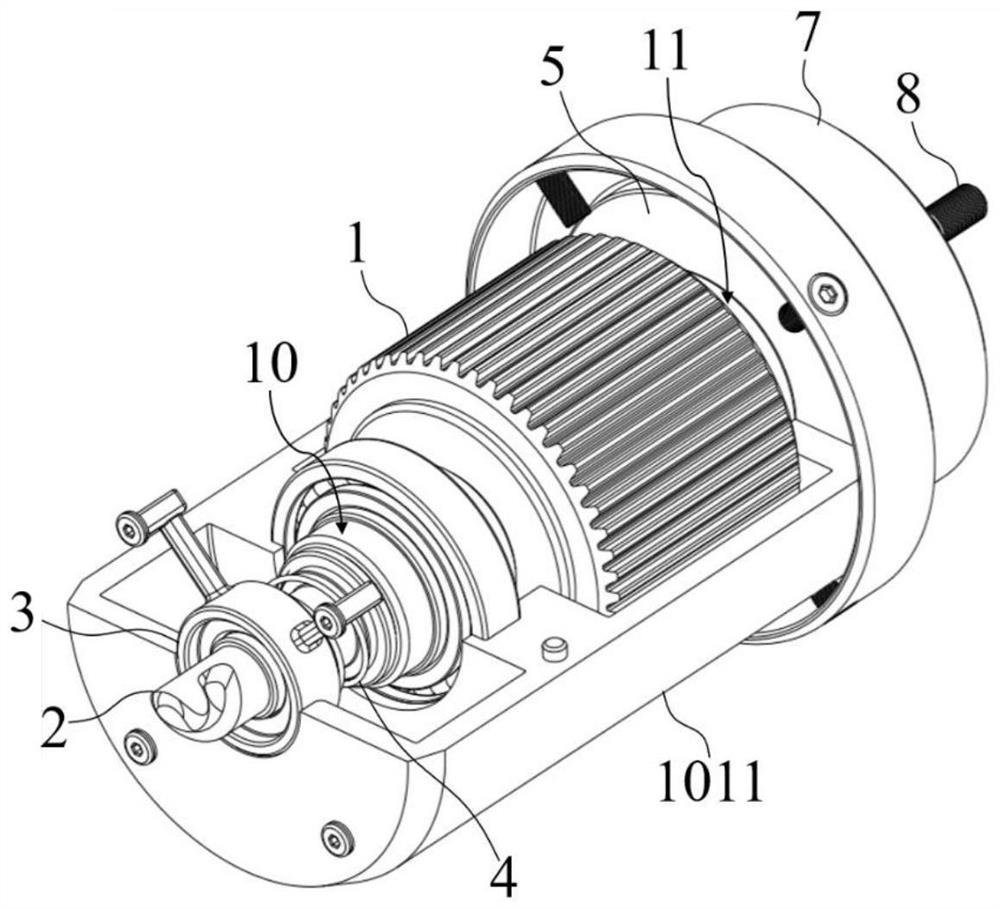
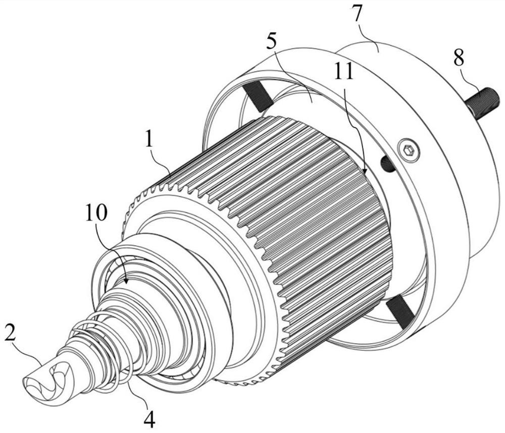
[0089] This embodiment shows a structure of the clutch transmission and the output shaft of the present invention, such as figure 1 and figure 2 As shown, the clutch transmission member is a threaded ring 3, which is a ring member with threads provided on the inner wall;

[0090] The output shaft is the output shaft A2, one end of which is drive-connected with the output end of the driver 1, and the other end passes through the threaded ring 3 and protrudes;

[0091] The part of the output shaft A2 located between the threaded ring 3 and the driving member 1 is formed with a threaded segment A20, a straight segment A21 and a limit ring 22 in sequence. In cooperation, the wall surface of the straight section A21 is straight, and the limiting ring 22 is formed on the wall surface of the output shaft A protrudingly.

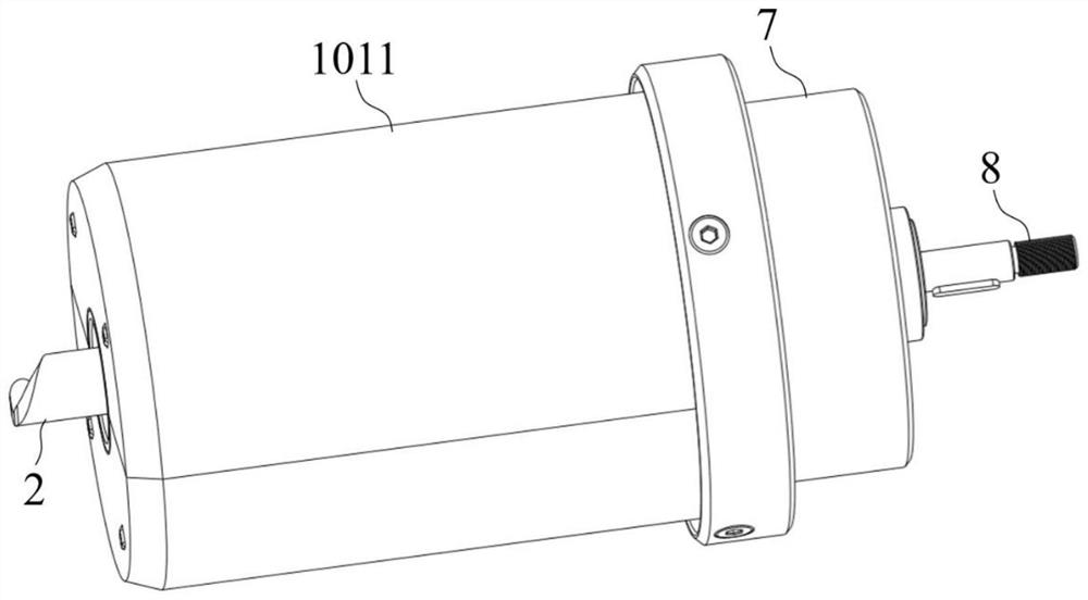
[0092] In this embodiment, the driving member 1 is the motor, which is placed in the figure 1 In the housing 1011 shown, in order to protect...

Example Embodiment

[0095] Example 3

[0096] In the bidirectional transmission method of this embodiment, both ends of the motor use the clutch transmission member and the output shaft A2 described in Embodiment 2. When the motor rotates forwardly, the output shaft A2 at one end extends and is connected to the external transmission mechanism for external transmission. The output shaft A2 at the other end retracts into the housing 1011 and does not transmit externally. When the motor reverses, the output shaft A2 at one end retracts to stop external transmission, and the output shaft A2 at the other end extends for external transmission.

[0097] Through the bidirectional transmission method of this embodiment, the purpose of bidirectional conversion transmission can be achieved by using a simple clutch transmission structure. Compared with the prior art, the method has less wear and consumption, is less prone to failure, and has low manufacturing and maintenance costs. .


PUM

PropertyMeasurementUnit
Diameteraaaaaaaaaa
Diameteraaaaaaaaaa

Abstract

The invention discloses a bidirectional transmission conversion device and a transmission method thereof, and belongs to the field of mechanical transmission. The device comprises an actuator for providing driving force, output ends being arranged at two ends of the actuator, and the actuator being capable of rotating forwards and backwards; the device also comprises two output shafts in transmission connection with the output ends of the actuator correspondingly; and two clutch transmission pieces arranged at the two ends of the actuator and in transmission connection with the corresponding output shafts through thread pairs respectively; and under the action of forward and reverse rotation of the actuator, the output shafts move relative to the corresponding clutch transmission pieces inaxis directions of the output shafts. The purpose of two-way transmission conversion can be achieved through the simple clutch transmission structure, and compared with the prior art, the device is small in abrasion consumption, not prone to breaking down and low in manufacturing cost and maintenance cost in a using process.

Description

technical field [0001] The invention belongs to the field of mechanical transmission, and more specifically relates to a bidirectional transmission conversion device and a transmission method thereof. Background technique [0002] At present, the transporter needs to use the transmission device to transmit power to move during use, and it is often necessary to carry out selective transmission connection according to the different requirements of the motion state to output different speeds. [0003] Under the development trend of portable and multi-functional vehicles, selective clutch transmission is no longer applicable to the transmission form that takes up a lot of space such as multi-drive parts. Instead, it can realize two-way transmission conversion through forward and reverse rotation. device, the existing device needs to be equipped with a complex clutch for selective clutching, which has the problems of high cost consumption, easy damage, and high maintenance cost. ...

Claims


Application Information

Patent Timeline
IPC IPC(8): F16D41/00F16H1/32B60K8/00B62K11/00
CPCB60K8/00B62K11/00B62K2202/00F16D41/00F16H1/32F16H2001/327
Inventor 汪磊高梦娟李春波杜卓然彭博常金成魏雨倩刘磊董育伟
Owner 软丰科技(江苏)有限公司淮安分公司
Why Eureka
Try Eureka