A bidirectional transmission conversion device and transmission method thereof
A two-way transmission and conversion device technology, which is applied in transmission devices, gear transmission devices, power devices, etc., can solve the problems of high wear consumption and inconvenient use in actual use, and achieve the effect of not easy to break down, simple in structure, and low in failure rate
- Summary
- Abstract
- Description
- Claims
- Application Information
AI Technical Summary
Problems solved by technology
Method used
Image
Examples
Embodiment 1
[0077] The two-way transmission conversion device of this embodiment includes:
[0078] The driving part 1, which provides the driving force, has output terminals at both ends, and the driving part 1 can rotate forward and reverse;
[0079] Also includes:
[0080] There are two output shafts, which are respectively connected to the output end of the driving member 1 in a driving manner; and
[0081] There are two clutch transmission parts, which are arranged at both ends of the drive part 1, and are respectively connected to the corresponding output shafts through threaded auxiliary transmission;
[0082] Under the forward and reverse action of the driving member 1, the output shaft is displaced along the axial direction of the output shaft relative to the corresponding clutch transmission member.
[0083] The existing two-way transmission conversion devices all need to be equipped with complex clutches for selective clutching, which has the problems of high cost consumption...
Embodiment 2
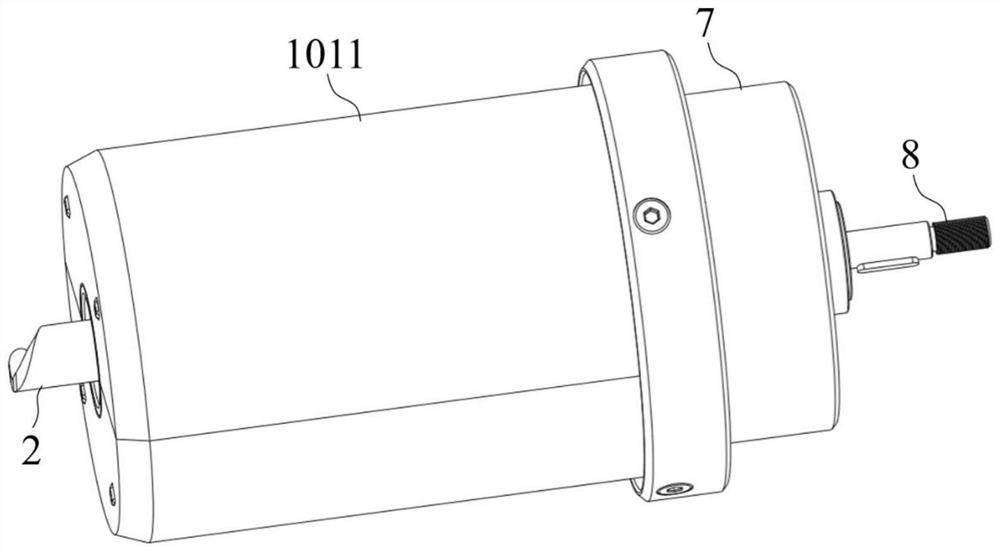
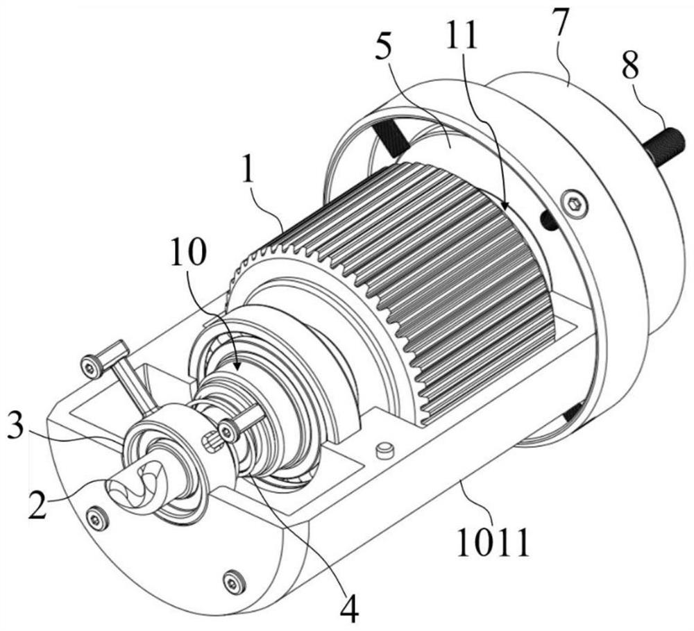
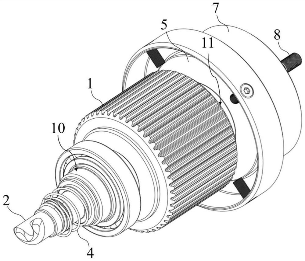
[0089] This embodiment shows a structure of the clutch transmission and the output shaft of the present invention, as figure 1 and figure 2 As shown, the clutch transmission part is a threaded ring 3, which is a threaded ring on the inner wall;
[0090] The output shaft is the output shaft A2, one end of which is connected to the output end of the driver 1 in a transmission manner, and the other end passes through the threaded ring 3 and protrudes;
[0091] The part of the output shaft A2 located between the threaded ring 3 and the driver 1 is sequentially formed with a threaded section A20, a straight section A21 and a limit ring 22. Matching, the wall surface of the straight section A21 is straight, and the limiting ring 22 is formed on the wall surface of the output shaft A with protrusions.
[0092] In this embodiment, the drive member 1 is the motor, placed as figure 1 In the shown housing 1011, in order to protect each component of the device and fix the position of ...
Embodiment 3
[0096] In the two-way transmission method of this embodiment, both ends of the motor adopt the clutch transmission member and the output shaft A2 described in Embodiment 2. When the motor rotates forward, the output shaft A2 at one end stretches out and is connected to the external transmission mechanism for external transmission. The output shaft A2 at the other end is retracted into the casing 1011 without external transmission. When the motor reverses, the output shaft A2 at one end is retracted to stop external transmission, and the output shaft A2 at the other end is stretched out for external transmission.
[0097] Through the two-way transmission method of this embodiment, the purpose of two-way conversion transmission can be achieved by using a simple clutch transmission structure. Compared with the prior art, this method has less wear and consumption, is less prone to failure, and has low manufacturing and maintenance costs. .
PUM
 Abstract
Description
Claims
Application Information
 - R&D
- Intellectual Property
- Life Sciences
- Materials
- Tech Scout
- Unparalleled Data Quality
- Higher Quality Content
- 60% Fewer Hallucinations
Browse by: Latest US Patents, China's latest patents, Technical Efficacy Thesaurus, Application Domain, Technology Topic, Popular Technical Reports.
© 2025 PatSnap. All rights reserved.Legal|Privacy policy|Modern Slavery Act Transparency Statement|Sitemap|About US| Contact US: help@patsnap.com


