Dfig unbalanced power grid voltage compensation method based on self-synchronous control without phase-locked loop

A technology of grid voltage and compensation method, applied in the direction of reducing the asymmetry of the polyphase network, eliminating/reducing the asymmetry of the polyphase network, electrical components, etc., can solve the problems that threaten the operating performance of the unit, the complex structure, and the high dependence of motor parameters , to achieve the effect of taking into account its own operation performance and power grid power quality, flexible compensation

Active Publication Date: 2021-10-08
ZHEJIANG UNIV +1
View PDF0 Cites 1 Cited by
  • Summary
  • Abstract
  • Description
  • Claims
  • Application Information

AI Technical Summary

Problems solved by technology

However, the traditional unbalanced voltage compensation method based on PCC voltage closed-loop has some shortcomings: 1) In the voltage closed-loop, the reference value of the negative sequence voltage can only be set to 0, which will seriously threaten the operation performance of the unit; 2) It is necessary to extract the positive and negative sequence components of voltage and current, and control it in multiple rotating coordinate systems. The structure is complex and highly dependent on motor parameters.
However, under non-ideal grid conditions, the PLL cannot quickly and accurately track the grid voltage signal, which will affect the control of DFIG and have potential stability problems

Method used


Image

  • Dfig unbalanced power grid voltage compensation method based on self-synchronous control without phase-locked loop
  • Dfig unbalanced power grid voltage compensation method based on self-synchronous control without phase-locked loop
  • Dfig unbalanced power grid voltage compensation method based on self-synchronous control without phase-locked loop

Examples


Embodiment Construction

[0049] The technical solutions of the present invention will be described in detail with reference to the accompanying drawings and specific embodiments.

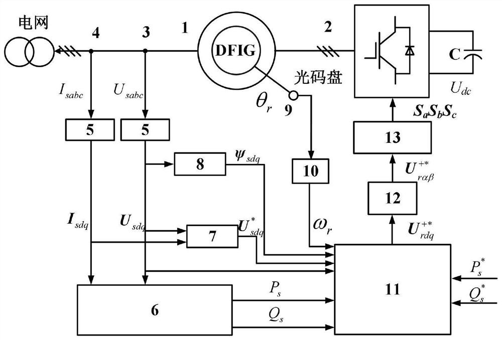
[0050] The system of non-loci-ring self-synchronous control DFIG unbalanced grid voltage compensation method is achieved figure 2 As shown, the system main includes a 1.65MW DFIG1, a voltage source converter 2 connected to a DFIG rotor winding, a stator three-phase voltage detector 3, a stator three-phase current detector 4, a three-phase coordinate system to a virtual DQ coordinate The coordinate transform module 5, the power calculation module 6, the negative voltage reference command value calculation module 7, the stator magnetic chain calculation module 8, the rotor position detects the optical display disc 9, the rotational speed differentter 10, the rotor command reference voltage calculation 11, the virtual DQ The rotating coordinate is between the two-phase stationary coordinate system transform module 12, and the SVPW...


PUM


Abstract

The invention discloses a DFIG unbalanced power grid voltage compensation method based on self-synchronization control without a phase-locked loop. On the basis of traditional direct power control, the method avoids the loss of the phase-locked loop by preset fixed rotation angle frequency dq coordinate system Introduced, by adding a direct resonator to compensate the unbalanced component of the grid voltage, without multiple coordinate transformations, the system control structure is simple, and it can quickly compensate when the grid voltage unbalance drops, improving the power quality of the grid. At the same time, the method of the invention can flexibly set the compensation coefficient, can realize the full-range compensation of the PCC voltage, and takes into account the power quality of the grid and the operating performance of the unit.

Description

Technical field [0001] The present invention belongs to the field of motor control technology, and more particularly to a DFIG unbalanced grid voltage compensation method based on non-locked-free ring-swimming control. Background technique [0002] Since the dual-feeder sensor (DFIG) has the advantages of small converter capacity, power flexibility and other advantages, DFIG-based wind turbines in new energy power generation is increasing, DFIG generator set system structure figure 1 Indicated. At present, my country's wind farm is mostly distributed in remote areas, and thus line impedance is large, usually in weak power grids; under weak grid conditions, wind power grid (PCC) typically exist large energy quality problems, such as voltage fluctuations, voltages Unbalance, etc. [0003] Due to the randomness of wind power, DFIG-based generator sets typically operate below the rated power, so the redundancy capacity of the unit is used to participate in the quality of the grid ele...

Claims


Application Information

Patent Timeline
Patent Type & Authority Patents(China)
IPC IPC(8): H02J3/38H02J3/46H02J3/26
CPCH02J3/26H02J3/381H02J3/46H02J2203/20H02J2300/28Y02E40/50
Inventor 年珩童豪秦世耀李少林贺敬
Owner ZHEJIANG UNIV
Why Eureka
Try Eureka