Printing table of automatic screen printer

A technology for screen printing machines and printing tables, which is applied to screen printing machines, printing machines, rotary printing machines, etc., can solve problems such as inability to effectively drain, reduce screen printing quality, and affect production efficiency, so as to improve production efficiency, Guarantee the effect of silk screen quality

Pending Publication Date: 2020-11-13
JIANGXI MULINSEN OPTOELECTRONICS TECH CO LTD
View PDF0 Cites 0 Cited by
  • Summary
  • Abstract
  • Description
  • Claims
  • Application Information

AI Technical Summary

Problems solved by technology

[0003] 1. Different batches of circuit boards have different numbers and distribution positions of through holes. When replacing circuit board batches, it is necessary to replace the corresponding printing table panel, because the disassembly and installation of the printing table is more complicated, which will affect the production efficiency. The high frequency of loading will affect the stability of the printing table and reduce the quality of silk screen printing
[0004] 2. The air in the through hole is usually squeezed out by the scraper and the ink during the silk screen printing of the existing circuit board, and it may not be effectively exhausted, which will affect the coating quality of the ink on the inner wall of the through hole
[0005] 3. After a period of use, there will be ink accumulation in the holes on the printing table panel. If it is not treated for a long time, it will dry and agglomerate, blocking the holes and affecting the quality of silk screen printing.

Method used


Image

  • Printing table of automatic screen printer
  • Printing table of automatic screen printer
  • Printing table of automatic screen printer

Examples


Embodiment Construction

[0027] The following will clearly and completely describe the technical solutions in the embodiments of the present invention with reference to the accompanying drawings in the embodiments of the present invention. Obviously, the described embodiments are only some, not all, embodiments of the present invention. Based on the embodiments of the present invention, all other embodiments obtained by persons of ordinary skill in the art without making creative efforts belong to the protection scope of the present invention.

[0028] In the description of the present invention, it should be understood that the terms "center, longitudinal, transverse, length, width, thickness, up, down, front, back, left, right, vertical, horizontal, top, bottom, inner, outer , clockwise, counterclockwise” and other indicated orientations or positional relationships are based on the orientations or positional relationships shown in the drawings, which are only for the convenience of describing the pre...


PUM


Abstract

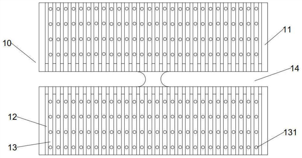
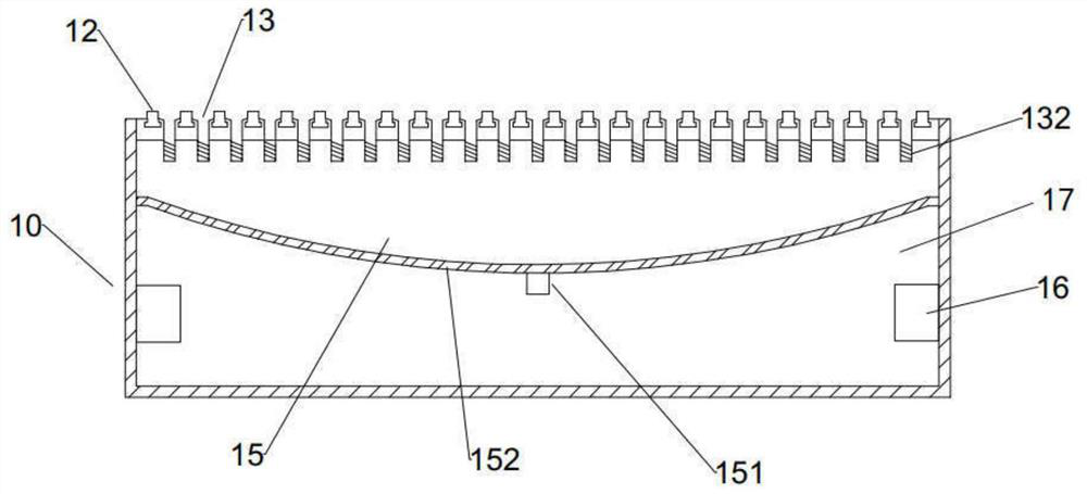
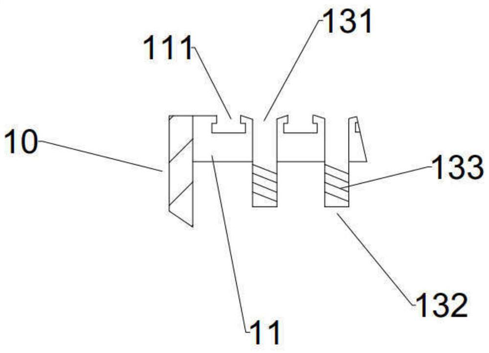
The invention relates to the technical field of circuit board printing equipment and particularly relates to a printing table of an automatic screen printer. The printing table comprises a printing table main body, wherein the upper end of the printing table main body is a printing table panel; multiple supporting rod and multiple ventilated grooves are disposed on the printing table panel; the printing rods and the ventilated grooves are mutually parallel and distributed at intervals; a straight groove used for motion of a transmission mechanism is formed in the center of the printing table main body; the transmission mechanism transmits a circuit board to the printing table panel so as to press the circuit board against the supporting rods; and the supporting rods are in dismountable connection with the printing table panel. According to the invention, the circuit board is transmitted to the supporting rods; the circuit board is supported by the supporting rods, so that a through hole in the circuit board is corresponding to the ventilated groove; a corresponding hole in the printing table panel is not needed; and in view of the fact that through holes in different batches of circuit boards have different positions, through dismounting and installation of the supporting rods, the through hole on the circuit board can be corresponding to the ventilated groove, and a new printing table panel does not need to be replaced.

Description

technical field [0001] The invention relates to the technical field of circuit board printing equipment, in particular to a printing table of an automatic screen printing machine. Background technique [0002] For the printing of circuit boards in the market, the general process is, firstly, the substrate is transferred to the printing platform through the feeding and handling mechanism, and then the ink is printed on the substrate through the screen printing mechanism, and there are usually many through holes on the substrate. , during screen printing, the inner wall of the through hole often needs to be covered with ink. It is bonded together with the printing table. For this, the existing printing table panel is usually provided with holes corresponding to the through holes on the circuit board, which is convenient to discharge the air in the through holes during silk screen printing and improve the quality of silk screen printing. However, the existing printing table Th...

Claims


Application Information

Patent Timeline
Patent Type & Authority Applications(China)
IPC IPC(8): B41F15/16B41F15/18
CPCB41F15/16B41F15/18
Inventor 周斌华罗丽光闫玲
Owner JIANGXI MULINSEN OPTOELECTRONICS TECH CO LTD
Why Eureka
Try Eureka