

Auxiliary unloading device for logistics transportation
An unloading device and logistics technology, applied in transportation and packaging, conveyor objects, loading/unloading, etc., can solve problems such as damage, waste of manpower, inconvenient cargo handling and storage, and achieve the effect of avoiding damage
- Summary
- Abstract
- Description
- Claims
- Application Information
AI Technical Summary
Problems solved by technology
Method used
Image

Examples
Embodiment Construction
[0017] All features disclosed in this specification, or steps in all methods or processes disclosed, can be combined in any way, except for mutually exclusive features and or steps.
[0018] Combine below Figure 1-5 The present invention is described in detail, and for convenience of description, the orientations mentioned below are now stipulated as follows: figure 1 The up, down, left, right, front and back directions of the projection relationship itself are the same.
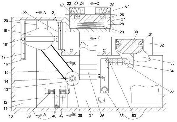
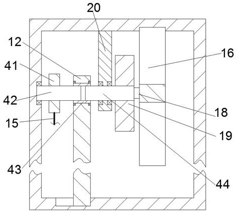
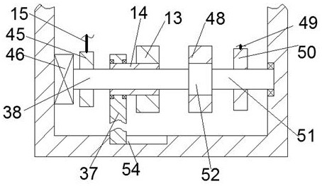
[0019] An auxiliary unloading device for logistics transportation of the device of the present invention includes an installation box 10, an installation cavity 11 is provided in the installation box 10, and an installation cavity 11 is provided in the installation cavity 11 to clamp the transported goods that need to be unloaded to avoid falling. The clamping mechanism 64 that falls and lifts. The clamping mechanism 64 includes a rack 36 that is slidably installed on the upper end wall of the installation...
PUM
 Abstract
Description
Claims
Application Information