Joint point coordinate obtaining method and device, and electronic equipment

An acquisition method and joint point technology, which is applied in the field of computer vision and can solve the problem that the depth camera cannot obtain the user's joint point coordinates.

Pending Publication Date: 2020-11-13
北京西米兄弟未来科技有限公司
View PDF0 Cites 0 Cited by
  • Summary
  • Abstract
  • Description
  • Claims
  • Application Information

AI Technical Summary

Problems solved by technology

[0004] The purpose of the embodiments of the present application is to provide a method, device and electronic device for obtaining joint point coordinates, which can solve the problem that the depth camera cannot obtain the user's joint point coordinates when the user is facing away from or facing the depth camera sideways

Method used


Image

  • Joint point coordinate obtaining method and device, and electronic equipment
  • Joint point coordinate obtaining method and device, and electronic equipment
  • Joint point coordinate obtaining method and device, and electronic equipment

Examples


Embodiment Construction

[0034] The following will clearly and completely describe the technical solutions in the embodiments of the present application with reference to the drawings in the embodiments of the present application. Obviously, the described embodiments are part of the embodiments of the present application, not all of them. Based on the embodiments in this application, all other embodiments obtained by persons of ordinary skill in the art without making creative efforts belong to the scope of protection of this application.

[0035] The terms "first", "second" and the like in the specification and claims of the present application are used to distinguish similar objects, and are not used to describe a specific sequence or sequence. It should be understood that the terms so used are interchangeable under appropriate circumstances such that the embodiments of the application can be practiced in sequences other than those illustrated or described herein, and that references to "first," "sec...


PUM


Abstract

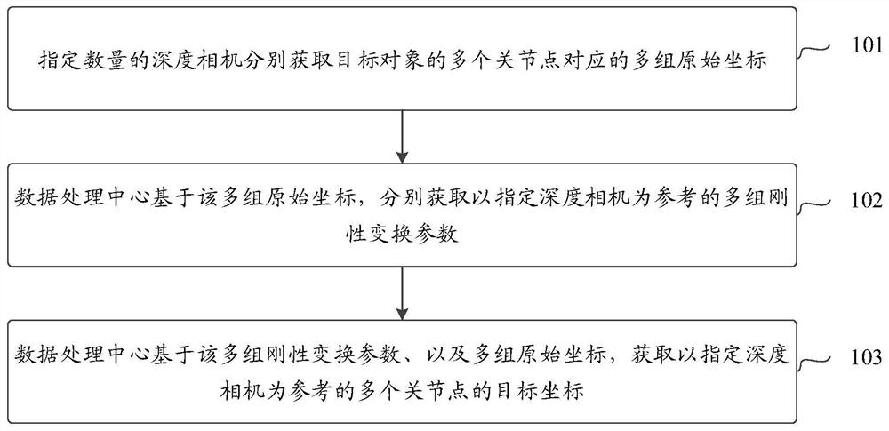
The invention discloses a joint point coordinate obtaining method and device, and electronic equipment and belongs to the technical field of computer vision. The method comprises steps that a specified number of depth cameras obtain multiple sets of original coordinates corresponding to multiple joint points of a target object, one set of original coordinates corresponding to one joint point of the target object comprise the specified number of original coordinates, and one set of original coordinates are obtained by collecting one joint point of the target object through the specified numberof depth cameras; the data processing center respectively acquires multiple groups of rigid transformation parameters taking the specified depth camera as a reference based on the multiple groups of original coordinates, one group of rigid transformation parameters corresponds to one group of original coordinates, and the specified depth camera is pre-specified from a specified number of depth cameras; the data processing center obtains a plurality of target coordinates of a plurality of joint points with the specified depth camera as a reference based on a plurality of sets of rigid transformation parameters and a plurality of sets of original coordinates, and one set of rigid transformation parameters corresponds to one target coordinate.

Description

technical field [0001] The present application belongs to the technical field of computer vision, and in particular relates to a method, device and electronic equipment for acquiring coordinates of joint points. Background technique [0002] With the rapid development of computer vision motion capture technology, the technical level of locating objects or human bodies is also constantly improving. In the prior art, the infrared optical positioning technology can usually obtain the three-dimensional coordinates of objects or human bodies at any position in the space by installing multiple emitters in the space. In addition, the traditional computer vision motion capture technology can use a depth camera to calculate the three-dimensional coordinates of the positioned object or human body based on the time difference and phase difference of light reflection emitted by the depth camera through Time of Flight (TOF) technology. [0003] In the process of implementing this applic...

Claims


Application Information

Patent Timeline
Patent Type & Authority Applications(China)
IPC IPC(8): G06T7/70G06T7/00
CPCG06T7/70G06T7/97G06T2207/10028
Inventor 师雪琴姚保岐
Owner 北京西米兄弟未来科技有限公司
Why Eureka
Try Eureka