
combing machine

A technology of combing machine and sliver, applied in the field of combing machine, can solve problems such as energy consumption, motor heating, motor life-span, motion control, response, etc.

Active Publication Date: 2022-06-07
MARZOLI MASCH TEXTILE SRL
View PDF5 Cites 0 Cited by
  • Summary
  • Abstract
  • Description
  • Claims
  • Application Information

AI Technical Summary

Problems solved by technology

[0016] However, this solution has significant disadvantages mainly related to energy consumption, heating of the motor, service life of such motors and response of the control to motion

Method used


Image

  • combing machine
  • combing machine
  • combing machine

Examples


Embodiment Construction

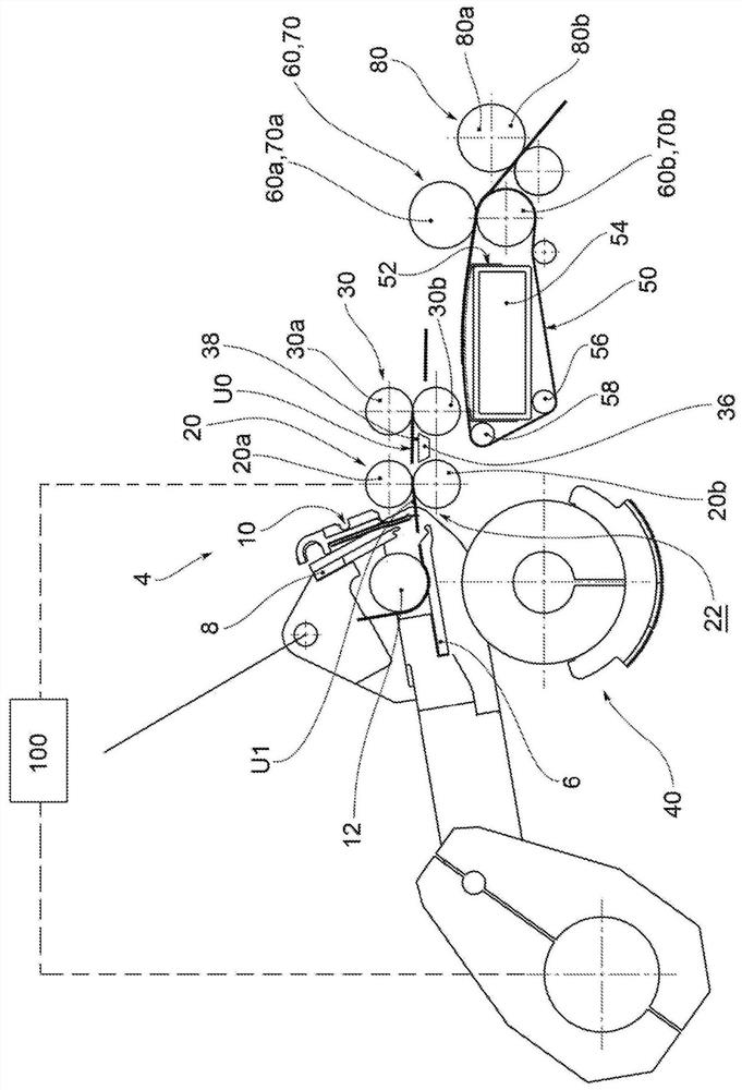
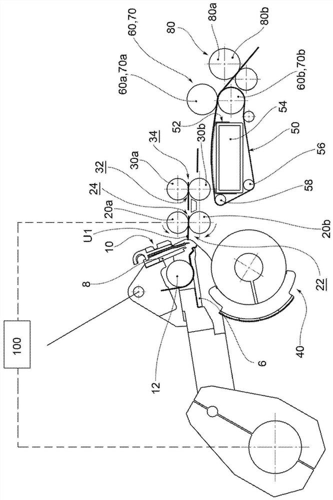
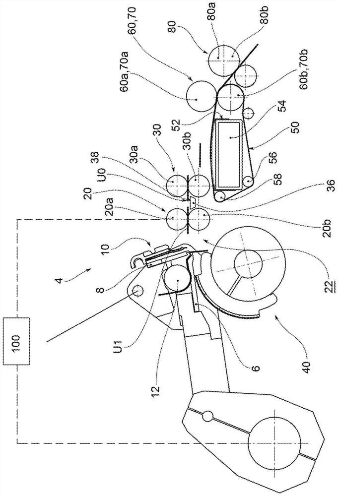
[0021] The combing machine according to the invention comprises a fixed frame and clamps 4 supported by the fixed frame.

[0022] The clamp 4 includes a lower jaw 6 , an upper jaw 8 and a straight comb 10 generally attached to the lower jaw 6 .

[0023] Furthermore, the gripper 4 includes a supply roller 12 supported by the lower jaw 6, which can be rotated intermittently on command.

[0024] The comber also includes a first pair of separation rolls 20 downstream of the nip 4, comprising an upper separation roll 20a and a lower separation roll 20b, which is typically pressure-coupled with the upper separation roll 20a and pulled in rotation therefrom.

[0025] Between said separating rollers 20a, 20b there is an inlet port 22 on one side of the gripper 4, which carries the sliver section that has been released by the supply roller 12, and an outlet port 24 on the other side.

[0026] The comber also includes a second pair of separation rolls 30 downstream of the first pair of...


PUM


Abstract

A combing machine comprising tongs (4) with a predetermined working speed (Vp) and a first pair of separating cylinders (20) with continuous rotary motion moving at an angular rotational speed (Wc). A management device (100) is provided to adjust the rotational speed (Wc) according to the working speed (Vp) of the tongs (4) such that the rotational speed (Wc) according to the working speed (Vp) is proportionally increased more.

Description

technical field [0001] The object of the present invention is a comber for a spinning preparation line. [0002] In the spinning preparation line, after the initial stage of opening and cleaning of the fibers, a carding process is envisaged by means of a carding machine, after which the fibers are presented in the form of slivers. [0003] After processing on a possible lap winder, in which several separated slivers are joined to obtain a lap, the sliver or lap is combed by a comber to obtain a lap in which the fibers are arranged highly parallel and clean nets. Background technique [0004] The basic combing operation at 450-500 strokes per minute in recent machines is: [0005] - intermittent supply of laps; [0006] - with the clamps closed, the head of the edge introduced by the rotary comb combing; [0007] - During the reverse rotation, the head of the edge is overlapped and joined by the separating rollers to the properly retracted web that has been combed in the ...

Claims


Application Information

Patent Timeline
Patent Type & Authority Patents(China)
IPC IPC(8): D01G19/26D01G19/18
CPCD01G19/26D01G19/18
Inventor 卢卡·索利亚尼吉罗拉莫·普兰迪尼
Owner MARZOLI MASCH TEXTILE SRL
Learn More