Illumination system for ophthalmic examination

A lighting system and ophthalmic examination technology, applied in the field of ophthalmic examination lighting systems, can solve problems such as distraction of doctors, influence on examination progress and examination results, inconvenience in use, etc., to achieve convenient and fast use, improve examination accuracy and examination efficiency , the effect of narrowing the light range

Inactive Publication Date: 2020-11-17
ZHENGZHOU RAILWAY VOCATIONAL & TECH COLLEGE
View PDF2 Cites 2 Cited by
  • Summary
  • Abstract
  • Description
  • Claims
  • Application Information

AI Technical Summary

Problems solved by technology

[0006] The ophthalmic lighting designed by the above-mentioned technical scheme is a desktop lighting. When used in combination with inspection equipment, the illuminatio

Method used


Image

  • Illumination system for ophthalmic examination
  • Illumination system for ophthalmic examination
  • Illumination system for ophthalmic examination

Examples


Embodiment 1

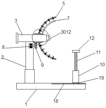
[0055] Such as figure 1 , 5 As shown in -7, a lighting system for ophthalmological examination; including a base 1 and an inspection mirror 3; a support rod 2 is connected above the base 1, and an inspection mirror 3 is arranged on the top of the support rod 2, and an inspection mirror 3 The interior of the inspection mirror 3 is provided with an inspection mechanism; the outside of the inspection mirror 3 is provided with a first gear ring 4, and the first gear ring 4 is rotationally connected with the outer wall of the inspection mirror 3; the support rod 2 is close to the inspection mirror 3 One end is provided with a first motor 8, the output shaft of the first motor 8 is driven and connected with a first gear 9, and the first gear 9 is meshed with the first gear ring 4, and the first gear 9 drives the first gear ring 4 rotation; the outer wall of the first toothed ring 4 is connected with a plurality of fixed rods 5, and the fixed rods 5 are provided with a plurality of ...

Embodiment 2

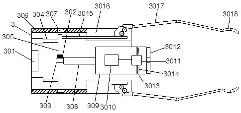
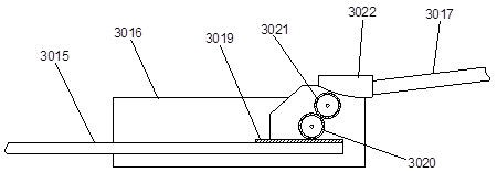
[0058] Such as Figure 2-4 As shown in and 8-10, the inspection mechanism provided inside the inspection mirror 3 includes a slide controller 301, which is connected to the side wall at one end of the inspection mirror 3, and two symmetrically arranged on the upper and lower sides of the slide controller 301. Telescopic rod 304, one end of two telescopic rods 304 is connected with inspection mirror 3, and the other end is connected with sliding rod 305, and the two ends of described sliding rod 305 are connected with slide block 307; The inner side wall of described inspection mirror 3 is symmetrical A chute 306 is provided, and the chute 306 is matched and slidably connected with the slider 307; a slider 302 is provided at the center of the slide bar 305, and the slider 302 is connected with the slide controller 301 by a wire, and the slide The device 302 is drivingly connected with a sliding gear 303, and the sliding gear 303 is in a sliding connection with the sliding rod 3...

Embodiment 3

[0065] Such as Figure 11 As shown, on the basis of Embodiment 1, in addition, the adjustment principle of the first lighting lamp 21 on the fixed rod 5: the first motor 8 drives the first gear 9 to rotate, the first gear 9 meshes to drive the first gear ring 4, the first A toothed ring 4 drives a plurality of fixed rods 5 to rotate, and further drives the first lighting lamp 21 to adjust the direction; The vertical height and horizontal distance from the eyeball are convenient for narrowing the local illumination range. In the case of low overall darkness, a uniform columnar light with a small range is produced to reduce eye irritation to patients; the first illuminating light 21 is provided with a shading plate 7 in the forward direction, and the width of the shading plate 7 is the same as that of the fixed installation, which can cover the light source of the first lighting lamp 21 on the fixed rod 5, so as to prevent the reflected light from shining in the eyes of the doct...


PUM


Abstract

The invention discloses a illumination system for ophthalmic examination. The illumination system comprises a base and an inspection mirror, wherein a first gear ring is arranged outside the inspection mirror in a sleeving manner, the first gear ring is rotatably connected with the outer side wall of the inspection mirror, a first motor is arranged at the end, close to the inspection mirror, of asupporting rod, an output shaft of the first motor is in driving connection with a first gear, the first gear is in engaged connection with the first gear ring, the first gear drives the first gear ring to rotate, a plurality of fixing rods are connected to the outer side wall of the first gear ring, a plurality of first illuminating lamps are arranged on the fixing rods, the end, away from the first motor, of the inspection mirror is sleeved with a lantern ring, the lantern ring is rotationally connected with the outer wall of the inspection mirror, and the outer side wall of the lantern ringis connected with a shading plate. According to the illuminating system, the illumination adjusting angle is large, different illumination angles can be adjusted according to the requirements of doctors, the brightness of local diffused light is increased, a uniform light source is generated in a small brightness area, and the inspection accuracy and the inspection efficiency can be improved.

Description

technical field [0001] The invention belongs to the field of ophthalmic examination lighting equipment, in particular to an illumination system for ophthalmic examination. Background technique [0002] Ophthalmological examination is a general examination of the eye, including examination of the ocular adnexa and anterior segment. Eye adnexa inspection includes eyelids, conjunctiva, lacrimal apparatus, eyeball position, and orbital inspection; traditional ophthalmic inspection equipment requires the patient to cooperate with medical staff, and then the medical staff judges the patient's symptoms, which is a challenge to the medical staff's technical skills. The requirements are relatively high, and medical staff need to have rich work experience, and patients need to cooperate accurately. [0003] At the same time, the current ophthalmic examination equipment generally needs to use auxiliary light sources for illumination when examining patients. Most of them use flashlight...

Claims


Application Information

Patent Timeline
IPC IPC(8): A61B3/00
CPCA61B3/0008
Inventor 刘意舒宝童武卫严凯谷中秀李媛媛马玲贾士红
Owner ZHENGZHOU RAILWAY VOCATIONAL & TECH COLLEGE
Why Eureka
Try Eureka