Vision detection system based on adjustable light

A vision detection and light adjustment technology, applied in the field of ophthalmic instruments, can solve problems such as inability to perform accurate detection

Inactive Publication Date: 2021-09-10
ZHENGZHOU RAILWAY VOCATIONAL & TECH COLLEGE
View PDF2 Cites 0 Cited by
  • Summary
  • Abstract
  • Description
  • Claims
  • Application Information

AI Technical Summary

Problems solved by technology

The above-mentioned technical solution adopts the traditional visual acuity test table for detection, which can only roughly detect whether myopia is present, and cannot perform accurate detection

Method used


Image

  • Vision detection system based on adjustable light
  • Vision detection system based on adjustable light
  • Vision detection system based on adjustable light

Examples


Embodiment 1

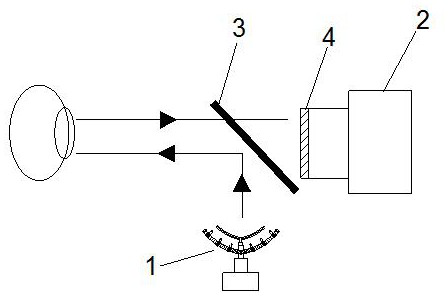
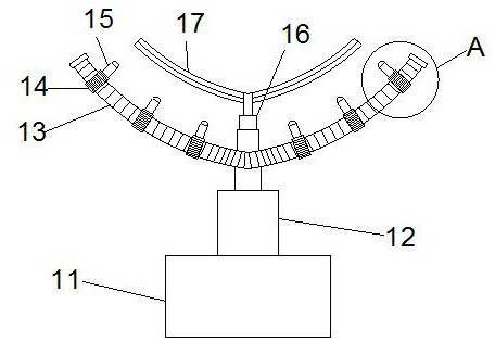
[0046] like figure 1 As shown, a vision detection system based on adjustable light; includes a camera 2, a half-return mirror 3 of the board head; a lighting mechanism 1 is arranged below the half-return mirror 3 of the board head, and the lighting mechanism 1 performs light adjustment, so The lighting mechanism 1 includes a base 11, a first motor 12 is arranged above the base 11, the output shaft of the first motor 12 is driven and connected with an arc-shaped screw rod 13, and the arc-shaped screw rod 13 is provided with a plurality of lighting bodies 15, The illuminating body 15 is provided with an infrared spotlight 1511 inside, and the infrared spotlight 1511 is connected with an adjustment mechanism, and the adjustment mechanism adjusts the beam angle, focal length, and beam distance of the infrared spotlight 1511. Illumination mechanism 1 injects infrared light into the human eye through the half-return mirror 3 of the board head, refracts the human eye, and then inject...

Embodiment 2

[0048] like Figure 2-5 , 7, on the basis of Embodiment 1, the output shaft of the first motor 12 is connected to the center of the arc-shaped screw 13, and the side of the arc-shaped screw 13 away from the first motor 12 is connected with a second The output shafts of the motor 16 and the second motor 16 are driven and connected with a shading plate 17, which is transparent or non-transparent, colored or colorless, and has a multi-layer structure.

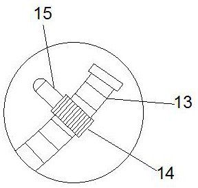
[0049] One end of the illuminating body 15 provided on the arc screw 13 is provided with an internal thread ring 14, and the internal thread ring 14 is matched and rotationally connected with the arc screw 13; the arc screw 13 is connected with the first motor 12 The same number of illuminating bodies 15 are set on both sides of the center of the output shaft.

[0050] The central position of the outer wall of the internally threaded ring 14 is provided with a "I" type chute 19 along the circumference, and the central position of...

Embodiment 3

[0053] like Image 6 , 8 As shown, on the basis of the first embodiment, the interior of the illuminating body 15 is a hollow structure, the interior of the illuminating body 15 is provided with a partition 152, and one side of the partition 152 is provided with a third motor 151. The output of the three motors 151 runs through the partition 152 and is connected with a coupling 153, the other end of which is connected with a threaded rod 154, and the threaded rod 154 is provided with an adjustment mechanism.

[0054] The adjustment mechanism includes a fixed plate 155, the central position of the fixed plate 155 is provided with a threaded hole, the fixed plate 155 is matched and rotated with the threaded rod 154 through the threaded hole, and the side of the fixed plate 155 away from the shaft coupling 153 is provided There are two support plates 156 symmetrically connected, and the other ends of the two support plates 156 are connected with a connecting plate 1510, and the ...


PUM


Abstract

The invention discloses a vision detection system based on adjustable light. The vision detection system comprises a camera and a semi-transparent and semi-reflective mirror; an illumination mechanism is arranged below the semi-transparent and semi-reflective mirror; the illumination mechanism performs illumination adjustment, and the illumination mechanism comprises a base; a first motor is arranged above the base; an output shaft of the first motor is in driving connection with an arc-shaped screw rod; a plurality of illumination bodies are arranged on the arc-shaped screw rod, and infrared spotlights are arranged in the illumination bodies; and each infrared spotlight is connected with an adjusting mechanism, and the adjusting mechanism adjusts the light emission angle, the focal length and the light emission distance of the corresponding infrared spotlight. The illumination is comprehensively adjusted and interacts with each other, so that the illumination for vision detection meets relatively high requirements, the accuracy of shot pictures is improved, and the detection error is reduced.

Description

technical field [0001] The invention belongs to the technical field of ophthalmic instruments, in particular to a vision detection system based on adjustable light. Background technique [0002] Good eyesight is an important part of health, and it is also an important factor to ensure an individual's independent life and quality of life. However, with the heavy school work of young people, the myopia of children and young people is gradually increasing. Wearing glasses too early not only affects children's life and learning , It also affects children's participation in sports activities and labor, resulting in low enthusiasm for children's participation, and even affecting the normal development of children, causing eye deformation and affecting image. Although the number of myopia patients is increasing, it can be restored to normal when detected early and treated in time. At present, pupil dilation and visual electrophysiological methods are mostly used for eye examinatio...

Claims


Application Information

Patent Timeline
Patent Type & Authority Applications(China)
IPC IPC(8): A61B3/103A61B3/00A61B3/15
CPCA61B3/103A61B3/0008A61B3/0075A61B3/154A61B3/0025
Inventor 刘意谷中秀李媛媛马宇马俊磊
Owner ZHENGZHOU RAILWAY VOCATIONAL & TECH COLLEGE
Why Eureka
Try Eureka