
Stone milling machine capable of controlling milling positions according to stone thickness

A technology of thickness control and milling machine, which is applied in the direction of machine tools suitable for grinding workpiece planes, grinding drive devices, and parts of grinding machine tools. It can solve the problem that the grinding and milling surface is not particularly smooth and tidy, and dust affects the surrounding environment. , increasing costs and other issues

Inactive Publication Date: 2020-11-17
福州袋书吧电子科技有限公司
View PDF0 Cites 1 Cited by
  • Summary
  • Abstract
  • Description
  • Claims
  • Application Information

AI Technical Summary

Problems solved by technology

[0002] Stone surface grinding is an indispensable step in stone processing. The existing stone milling machines only have manual control for grinding, which will cause the grinding surface to be not particularly smooth and tidy, and the long-term manual grinding will increase. The cost of production may also lead to some accidental factors. The dust after milling will also affect the surrounding environment. A stone milling machine that controls the milling position according to the thickness of the stone explained in the present invention can solve the above problems

Method used


Image

  • Stone milling machine capable of controlling milling positions according to stone thickness
  • Stone milling machine capable of controlling milling positions according to stone thickness
  • Stone milling machine capable of controlling milling positions according to stone thickness

Examples


Embodiment Construction

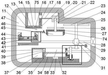
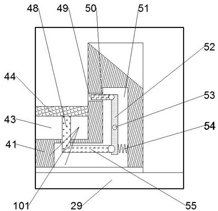
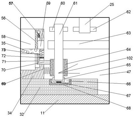
[0013] Combine below Figure 1-Figure 3 The present invention is described in detail, and for convenience of description, the orientations mentioned below are now stipulated as follows: figure 1 The up, down, left, right, front and back directions of the projection relationship itself are the same.

[0014] A stone milling machine according to the present invention, which controls the milling position according to the thickness of the stone, includes a processing body 11, a movement cavity 47 is opened in the processing body 11, and a right wall of the movement cavity 47 is fixed with a Large motor 28, the left end face of described large motor 28 is power-connected and is provided with screw rod 29, and described screw rod 29 extends left and stretches in the left wall of described motion chamber 47, and described motion chamber 47 is provided with slide clip Tightening mechanism 101, described sliding clamping mechanism 101 comprises the threaded slider 41 that is threadedl...


PUM


Abstract

The invention discloses a stone milling machine capable of controlling milling positions according to the stone thickness. The stone milling machine comprises a machining machine body, a moving cavityis formed in the machining machine body, and a large motor is fixedly embedded in the right wall of the moving cavity. The stone milling machine is mainly applied to being used for the surface milling procedure during stone machining. In the milling process, stone is clamped by a clamping block under the action of a sliding clamping mechanism, and then the situation that milling is influenced bystone moving is avoided; meanwhile, rotating of a milling cutter and moving of the stone can be achieved to a certain position to achieve automatic milling through abutting connection of a threaded sliding block and a cutter shell; meanwhile, water injection milling can be achieved on the surface of the stone through a water outlet pipeline; and particulate matter left after milling is synchronously cleaned through an engaging and jacking mechanism, a driven gear and a driving gear are engaged while a filter plate is stressed to move downwards, then an eccentric wheel is driven to move, and then the particulate matter is cleaned.

Description

technical field [0001] The invention relates to the related field of stone, in particular to a stone milling machine for controlling the milling position according to the thickness of the stone. Background technique [0002] Stone surface grinding is an indispensable step in stone processing. The existing stone milling machines only have manual control for grinding, which will cause the grinding surface to be not particularly smooth and tidy, and the long-term manual grinding will increase. The cost of production may also lead to some accidental factors. The dust after milling will also affect the surrounding environment. A stone milling machine that controls the milling position according to the thickness of the stone explained in the present invention can solve the above problems . Contents of the invention [0003] In order to solve the above problems, this example designs a stone milling machine that controls the milling position according to the thickness of the ston...

Claims


Application Information

Patent Timeline
Patent Type & Authority Applications(China)
IPC IPC(8): B24B7/02B24B27/00B24B41/06B24B47/00B24B47/12B24B47/22B24B55/06B24B55/12B24B57/02B01D29/03B01D29/64
CPCB01D29/03B01D29/6484B24B7/02B24B27/0069B24B41/06B24B47/00B24B47/12B24B47/22B24B55/06B24B55/12B24B57/02
Inventor 姜珊珊
Owner 福州袋书吧电子科技有限公司
Learn More