An ornamental stone groove opening twill device
A technology for ornamental stone troughs and twill patterns, applied in stone processing tools, stone processing equipment, work accessories, etc., can solve problems such as increased work difficulty, hidden safety hazards, and low work efficiency
- Summary
- Abstract
- Description
- Claims
- Application Information
AI Technical Summary
Problems solved by technology
Method used
Image
Examples
Embodiment 1
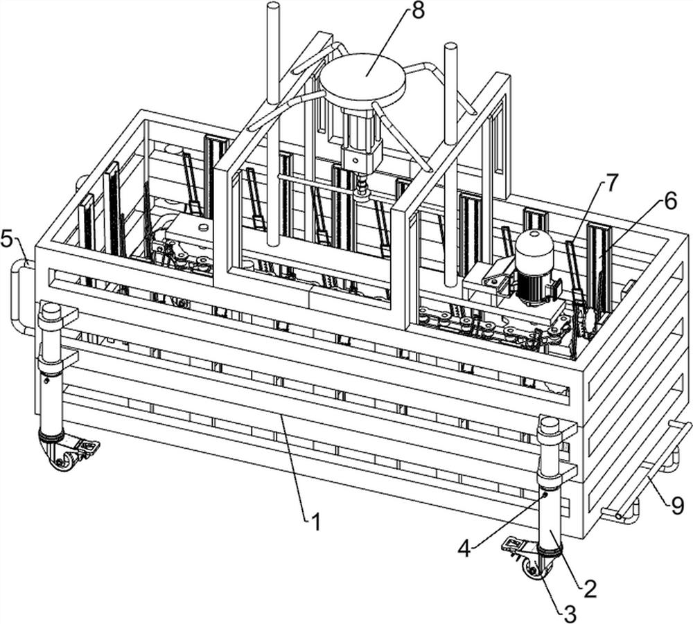
[0040] An ornamental stone groove opening twill device, such as figure 1 As shown, it includes a mounting frame 1, a telescopic rod 2, a universal wheel 3, a screw rod 4, a handle 5, a clamping mechanism 6 and a slotting mechanism 7. The two front sides of the mounting frame 1 are provided with a telescopic rod 2. The telescopic rod 2. There are universal wheels 3 at the bottom, screws 4 are arranged on the outer walls of the telescopic rods 2, handles 5 are arranged on the left and front of the mounting frame 1, and a clamping mechanism 6 is arranged on the inner wall of the installation frame 1, and the inner wall of the clamping mechanism 6 is provided with Slotting mechanism 7.
[0041] When the staff needs to twill the stone groove, they can first stretch the telescopic rod 2 upward, and then use the screw 4 to fix the telescopic rod 2, and then the staff can hold the handle 5 to move the device to the top of the stone groove to make the stone groove It is located under ...
Embodiment 2
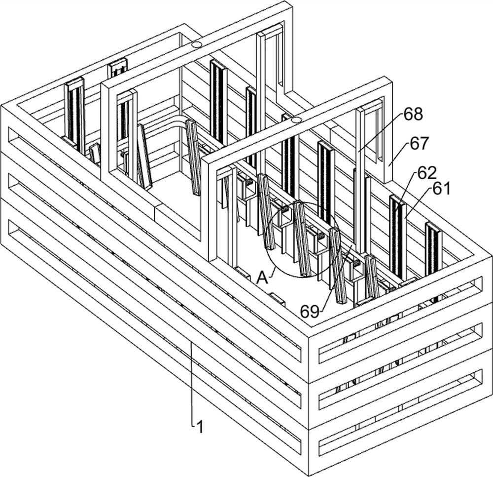
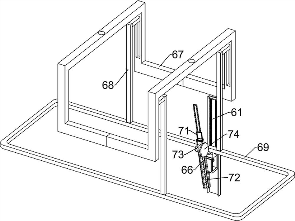
[0043] On the basis of Example 1, as Figure 2-3 As shown, the clamping mechanism 6 includes a first sliding rail 61, a first spring 62, a clamping plate 63, a first pressing plate 64, a second spring 65, a second sliding rail 66, a fixing frame 67, a first connecting rod 68 and The second pressing plate 69, the inner wall of the mounting frame 1 is provided with a first sliding rail 61, the first sliding rail 61 is slidably provided with a clamping plate 63, and the two sides of the top of the clamping plate 63 and the upper part of the inner wall of the first sliding rail 61 are A first spring 62 is provided, a second spring 65 is provided at the lower part of the inner wall of the clamping plate 63, the end of the second spring 65 is connected with a first pressing plate 64, a second sliding rail 66 is provided on the inner side of the upper part of the clamping plate 63, and the top of the mounting frame 1 A fixing frame 67 is provided between the two sides. The four walls...
PUM
 Abstract
Description
Claims
Application Information
 - R&D
- Intellectual Property
- Life Sciences
- Materials
- Tech Scout
- Unparalleled Data Quality
- Higher Quality Content
- 60% Fewer Hallucinations
Browse by: Latest US Patents, China's latest patents, Technical Efficacy Thesaurus, Application Domain, Technology Topic, Popular Technical Reports.
© 2025 PatSnap. All rights reserved.Legal|Privacy policy|Modern Slavery Act Transparency Statement|Sitemap|About US| Contact US: help@patsnap.com


