Rapid grooving equipment for indoor ground wire duct

A technology for indoor floor and grooving equipment, applied in stone processing equipment, work accessories, manufacturing tools, etc., can solve problems such as affecting the grooving effect, high work intensity, damage, etc.

Pending Publication Date: 2022-05-10
张顺顺
View PDF7 Cites 0 Cited by
  • Summary
  • Abstract
  • Description
  • Claims
  • Application Information

AI Technical Summary

Problems solved by technology

[0005] In order to overcome the shortcomings of the existing technology that still requires manual long-term hand-held slotting equipment for slotting, the work intensity is relatively high, and the tool is in contact with the ground for a long time, which is easy to cause damage and affect the slotting effect. Contact with the ground to ensure the slotting efficiency of the indoor ground trunking rapid slotting equipment

Method used


Image

  • Rapid grooving equipment for indoor ground wire duct
  • Rapid grooving equipment for indoor ground wire duct
  • Rapid grooving equipment for indoor ground wire duct

Examples


Embodiment 1

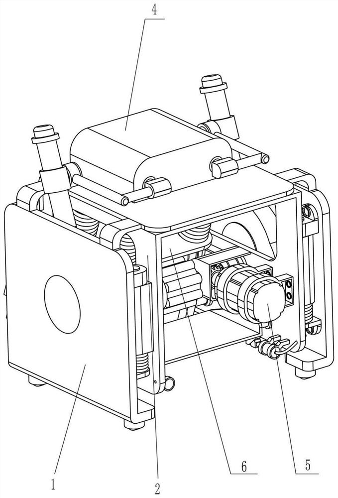
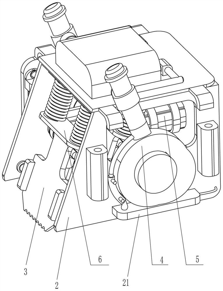
[0032] A kind of fast slotting equipment for indoor ground trunking, such as figure 1 , figure 2 , image 3 with Image 6 As shown, it includes a first fixed frame 1, a fixed frame 2, a hollow plate 21, a slotting knife 3, a guide block 31, a driving mechanism 5 and a sliding mechanism 6, and the first fixed frame 1 is slidingly provided with a fixed frame 2, Both sides of the lower part of the fixed frame 2 are provided with hollow plates 21, the inner wall of the lower part of the fixed frame 2 is provided with two guide blocks 31 on both sides, and the two guide blocks 31 on the same vertical side are slidingly installed with slots. Knife 3, the lower part of the slotting knife 3 is wave-shaped, which reduces the impact force while ensuring the quality of slotting. The slotting knife 3 moves up and down to slot the ground. The slotting knife 3 is located on the left side of the fixed frame 2, and the fixed frame 2 The inner right side is provided with a driving mechanis...

Embodiment 2

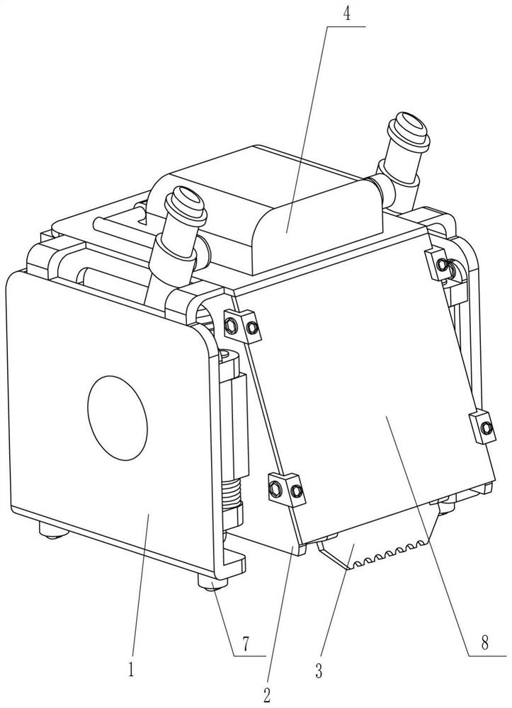
[0037] On the basis of Example 1, such as figure 1 , figure 2 , image 3 , Figure 4 , Figure 5 , Figure 7 with Figure 8 As shown, it also includes a lifting mechanism 4, which can drive the fixed frame 2 and the slotting knife 3 to move up and down to adjust the slotting height. 44, guide bar 45 and the first spring 46, first fixed mount 1 top is provided with cylinder 41, and the driving rod right side of cylinder 41 is connected with pushing frame 42 symmetrically front and rear, first fixed mount 1 inner wall front and rear both sides are all rotationally designed. Hinged cam 43 is arranged, and hinged cam 43 is in contact with hollow plate 21, and the periphery of hinged cam 43 is connected with swing rod 44, and swing rod 44 is all slidably connected with push frame 42 on the same side. Left and right symmetrical bolts are connected with guide rods 45 , and the guide rods 45 are all slidably connected to the outside of the fixed frame 2 , and a first spring 46 ...

Embodiment 3

[0041] On the basis of Example 2, such as figure 2 , Figure 9 with Figure 10 As shown, it also includes a moving device 8, which drives the entire slotting equipment to move easily. The moving device 8 includes a fixed ring 81, a hinged rod 82 and a moving wheel 83. The left and right sides of the bottom of the first fixed frame 1 are all symmetrical A fixed ring 81 is provided, and hinged rods 82 are hinged in the fixed rings 81, and movable wheels 83 are arranged on the hinged rods 82.

[0042] Also include protective device 9, protective device 9 can prevent stones from splashing and hurting personnel, protective device 9 includes second fixed block 91, protective plate 92 and fixed screw rod 93, the left side of both sides of fixed frame 2 front and back are all up and down symmetrically by fixing The second fixing block 91 is installed on the screw rod 93 , and the protective plate 92 is connected between the second fixing blocks 91 through the fixing screw rod 93 . ...


PUM


Abstract

The invention relates to slotting equipment, in particular to rapid slotting equipment for an indoor ground wire slot. Mainly provides the rapid grooving equipment for the indoor ground wire groove, which reduces the working intensity, drives a cutter to be in continuous contact with the ground and ensures the grooving efficiency. Rapid grooving equipment for indoor ground wire ducts comprises a first fixing frame, a fixing frame, hollow plates, grooving cutters, guide blocks and the like, the fixing frame is arranged in the first fixing frame in a sliding mode, the hollow plates are arranged on the front side and the rear side of the lower portion of the fixing frame, and the two guide blocks are arranged on the front side and the rear side of the inner wall of the lower portion of the fixing frame. Grooving cutters which move up and down to groove the ground are installed between the two guide blocks on the same side in the vertical direction in a sliding mode. The rolling cam rotates to be in contact with the grooving cutter continuously and extrudes the grooving cutter to move downwards continuously to be in contact with the ground, then the whole equipment is pushed to move through the moving wheels, and grooving of a circuit can be achieved.

Description

technical field [0001] The invention relates to a slotting device, in particular to a quick slotting device for indoor ground wire slots. Background technique [0002] In interior decoration, in order to ensure the aesthetics, the wires are often buried inside the wire grooves by opening wire grooves. During the slotting process, the decoration master will use a special slotting machine, which needs to be held for a long time when using it, and it is necessary to grasp the strength to fix the slotting depth, which will cause the master's arm to be tired and affect the slotting operation. [0003] The patent authorization announcement number is CN210100394U, which discloses a kind of wire slot slotting equipment for indoor decoration, including a slotting machine body, an external frame is arranged on the outside of the slotting machine body, and the left side of the external frame is A distance-adjustable frame is provided, the left side of the distance-adjustable frame is ...

Claims


Application Information

Patent Timeline
Patent Type & Authority Applications(China)
IPC IPC(8): B28D1/22B28D7/02B28D7/00
CPCB28D1/222B28D1/22B28D7/02B28D7/005B28D7/00
Inventor 张顺顺
Owner 张顺顺
Why Eureka
Try Eureka