
A keyway processing device for mass production

A mass production and processing device technology, which is applied in the direction of driving device, feeding device, positioning device, etc., can solve the problems of non-continuous processing, low processing efficiency, and batch processing, etc., and achieve a design with ingenious design, high processing efficiency and reasonable structure. Effect

Active Publication Date: 2020-12-22
马鞍山常裕机械设备股份有限公司
View PDF1 Cites 0 Cited by
  • Summary
  • Abstract
  • Description
  • Claims
  • Application Information

AI Technical Summary

Problems solved by technology

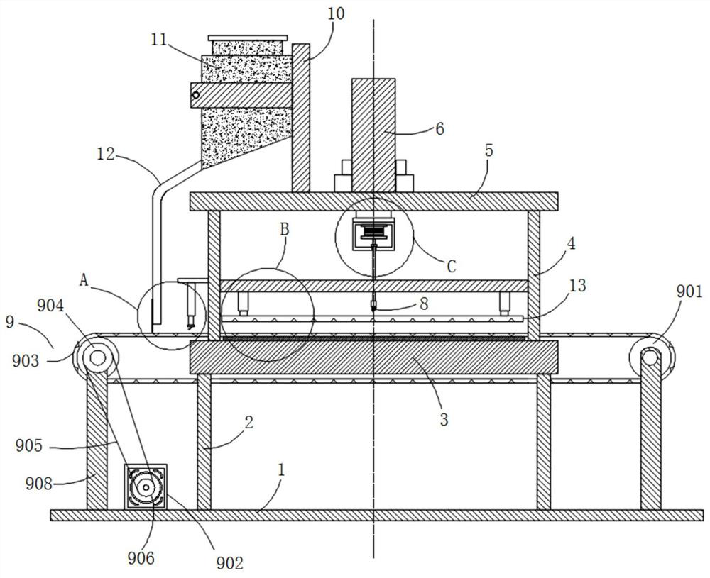
[0005] The purpose of the present invention is to solve the problems in the prior art that cannot be processed continuously, cannot be processed in batches, manual operation is required when fixing, the operation is cumbersome, and the processing efficiency is low, and a keyway processing device for batch production is proposed.

Method used


Image

  • A keyway processing device for mass production
  • A keyway processing device for mass production
  • A keyway processing device for mass production

Examples


Embodiment Construction

[0028] The following will clearly and completely describe the technical solutions in the embodiments of the present invention with reference to the accompanying drawings in the embodiments of the present invention. Obviously, the described embodiments are only some, not all, embodiments of the present invention.

[0029] In describing the present invention, it should be understood that the terms "upper", "lower", "front", "rear", "left", "right", "top", "bottom", "inner", " The orientation or positional relationship indicated by "outside", etc. is based on the orientation or positional relationship shown in the drawings, and is only for the convenience of describing the present invention and simplifying the description, rather than indicating or implying that the referred device or element must have a specific orientation, so as to Specific orientation configurations and operations, therefore, are not to be construed as limitations on the invention.

[0030] refer to Figure ...


PUM


Abstract

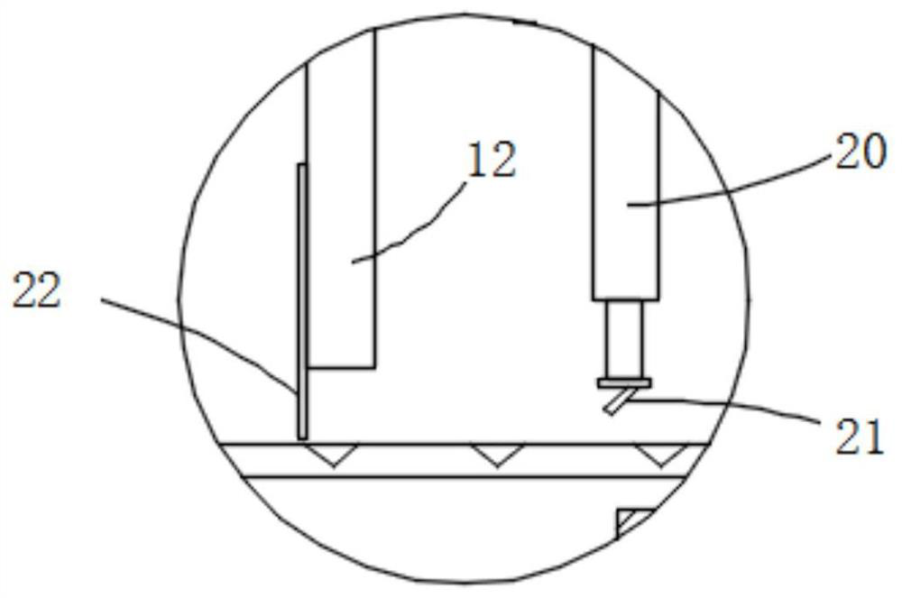
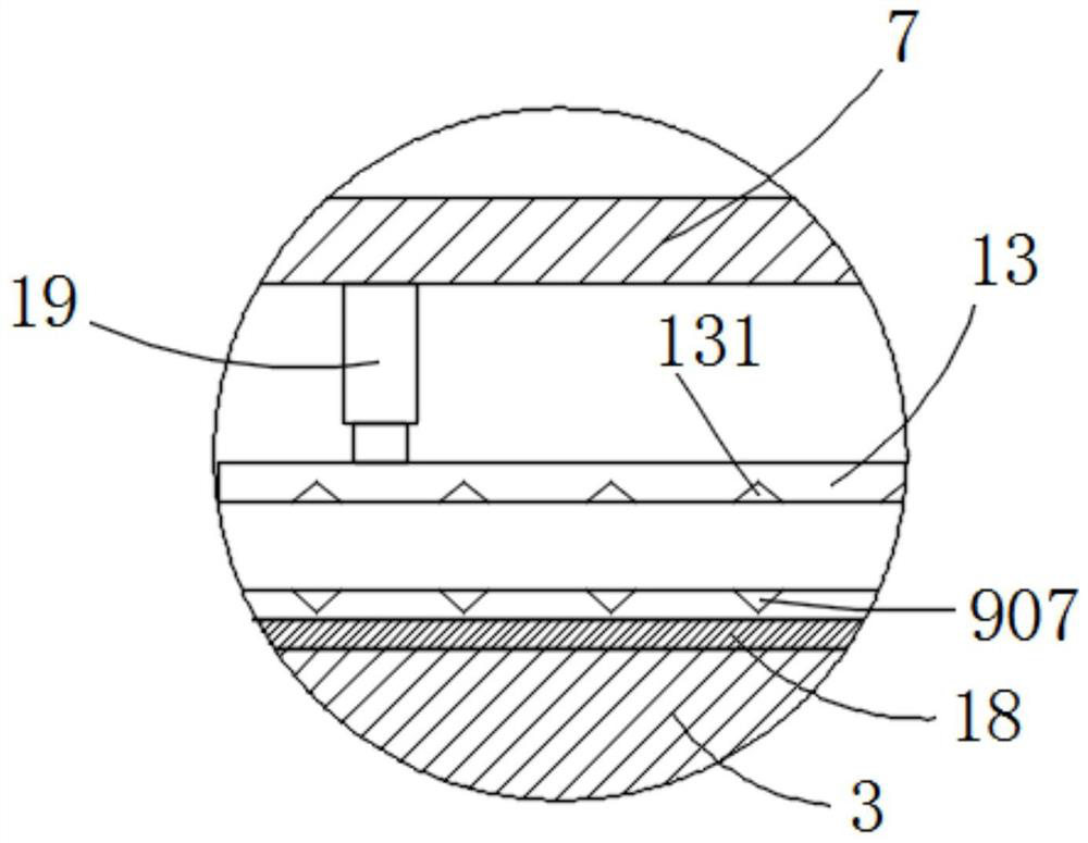
The invention discloses a key groove machining device for batch production. The key groove machining device comprises a base plate, wherein the top of the base plate is fixedly provided with a first supporting column, the upper end of the first supporting column is fixedly provided with a workbench in a cooperated mode, the top of the workbench is fixedly provided with a second supporting column,the upper end of the second supporting column is fixedly provided with a top plate in a cooperated mode, the center position of the top of the top plate is fixedly provided with a hydraulic machine ina cooperated mode, the piston end of the hydraulic machine faces downwards and is fixedly provided with a mounting box in a cooperated mode after penetrating through the top plate, the inner top of the mounting box is fixedly provided with a driving motor in a cooperated mode, a plurality of gears are arranged at the inner bottom of the mounting box in the width direction of the mounting box at intervals, the bottom parts of the gears are fixedly provided with driving shafts in a cooperated mode, the driving shafts are rotated to penetrate through the mounting box and then fixedly provided with milling cutters in a matched manner, the multiple gears are meshed with each other in a paired mode, and the output end of the driving motor is fixedly matched with the center of the top of one ofthe gears. According to the key groove machining device, the device has the advantages that the structure is reasonable, the design is ingenious, workpiece key grooves can be machined in batches, themachining efficiency is high, and the device is suitable for popularization and application.

Description

technical field [0001] The invention relates to the technical field of keyway processing devices, in particular to a keyway processing device for mass production. Background technique [0002] In modern production, machine tool fixtures have become an indispensable process equipment in machining as a part of machine tools. When the production batch of the workpiece is large, in addition to considering the machining accuracy of the workpiece, we also need to consider the productivity and economical issues. Therefore, a special fixture specially designed for a certain process of a certain part is often used to clamp the workpiece. In the existing keyway processing, most of the keyways are still single-piece clamping and milling keyways, which has low production efficiency and low precision. [0003] After retrieval, the patent application CN201510813873.9 proposes a keyway processing device, including a processing tool and a workpiece holder. The processing tool includes a ho...

Claims


Application Information

Patent Timeline
Patent Type & Authority Patents(China)
IPC IPC(8): B23C3/30B23Q5/10B23Q5/34B23Q3/08B23Q3/06
CPCB23C3/30B23Q3/06B23Q3/08B23Q3/082B23Q5/10B23Q5/34B23Q2703/04
Inventor 蔡发华
Owner 马鞍山常裕机械设备股份有限公司
Learn More