
Electrostatic flashing type wheel

A flashing, wheel technology, applied in the direction of wheels, wheel covers, vehicle parts, etc., can solve the problems of demagnetization of the magnet at the center of the wheel, the loss of the colorful effect of the LED bulb, the disappearance of the induced current of the induction coil, etc., to achieve stable lighting, The effect of small external interference factors and increasing the frequency of discharge flashes

Pending Publication Date: 2020-11-17
陈华连
View PDF4 Cites 1 Cited by
  • Summary
  • Abstract
  • Description
  • Claims
  • Application Information

AI Technical Summary

Problems solved by technology

[0005] The purpose of the present invention is to solve the problem in the prior art that "the bicycle wheel will continuously vibrate during the rolling process on the ground, which will easily lead to the demagnetization of the magnet at the center of the wheel, and then cause the induction current of the induction coil to disappear, causing the LED bulb The defect that the power is not turned on and the colorful effect is lost, thus a kind of electrostatic flashing wheel is proposed

Method used


Image

  • Electrostatic flashing type wheel
  • Electrostatic flashing type wheel

Examples


Embodiment Construction

[0018] The technical solutions in the embodiments of the present invention will be clearly and completely described below with reference to the accompanying drawings in the embodiments of the present invention. Obviously, the described embodiments are only a part of the embodiments of the present invention, but not all of the embodiments.

[0019] In describing the present invention, it should be understood that the terms "upper", "lower", "front", "rear", "left", "right", "top", "bottom", "inner", " The orientation or positional relationship indicated by "outside", etc. is based on the orientation or positional relationship shown in the drawings, and is only for the convenience of describing the present invention and simplifying the description, rather than indicating or implying that the referred device or element must have a specific orientation, so as to Specific orientation configurations and operations, therefore, are not to be construed as limitations on the invention. ...


PUM


Abstract

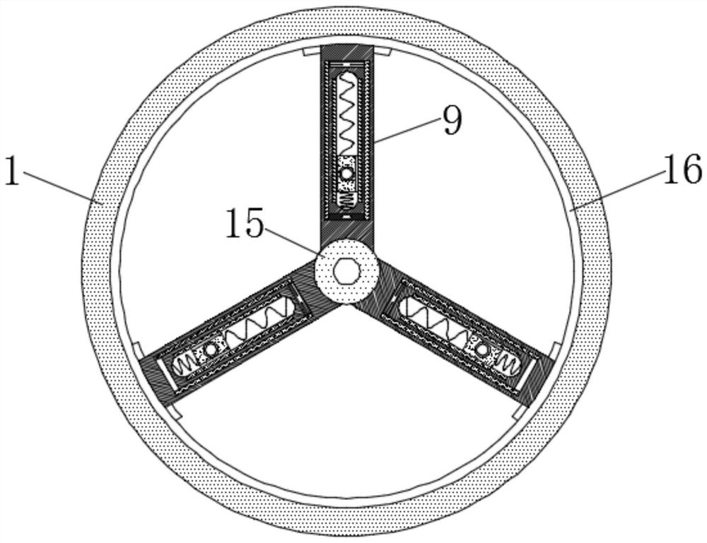
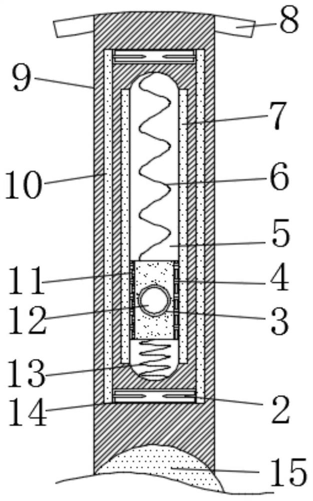
The electrostatic flashing type wheel comprises a center shaft, a hub and a tire, a plurality of supporting plates are fixedly installed on the side wall of the center shaft at equal intervals in an annular mode, the ends, deviating from the center shaft, of the multiple supporting plates are jointly and fixedly installed on the inner side wall of the hub, and the tire is fixedly connected to theouter side wall of the hub in a sleeving mode; a sliding cavity is formed in the center of each supporting plate, a sliding block is slidably connected into each sliding cavity, the upper end and thelower end of each sliding block are fixedly connected with the inner wall of the corresponding sliding cavity through a first spring and a second spring correspondingly, and silk and fur are bonded tothe left side and the right side of each sliding block correspondingly. And a glass screen plate and a rubber screen plate are fixedly mounted on the left side wall and the right side wall in the sliding cavity correspondingly, the rubber screen plate is slidably connected with the fur, and the glass screen plate is slidably connected with the silk. Compared with the prior art, the electrostaticflashing type wheel is small in external interference factor and can emit light stably.

Description

technical field [0001] The invention relates to the technical field of wheels, in particular to an electrostatic flash wheel. Background technique [0002] Bicycles are a very common means of travel, especially nowadays many young people like to ride bicycles when going to and from get off work, avoiding the morning and evening rush hours in the city. [0003] Existing bicycles are relatively monotonous during riding, so some people turn LED bulbs of various colors on the bracket of the wheel, and use the magnet on the wheel to cut the coil to generate an induced current during riding, and make it The light bulb emits colorful light, but the wheel will vibrate continuously when it rolls on the ground, which will easily cause the magnet at the center of the wheel to demagnetize, which will lead to the disappearance of the induced current of the induction coil, causing the LED bulb to lose its brightness when it is powered off. colorful effect. [0004] In order to solve the...

Claims


Application Information

Patent Timeline
Patent Type & Authority Applications(China)
IPC IPC(8): B60B7/00
CPCB60B7/006
Inventor 陈华连
Owner 陈华连
Learn More