
Damping supporting device for fan carrying

A technology of supporting device and fan, applied in the directions of transportation and packaging, packaging, and packaging food, etc., can solve the problems of complicated fixing process and damage to the fan, and achieve the effect of good transportation effect, avoiding side slip and avoiding damage.

Inactive Publication Date: 2020-11-17
梁佳
View PDF0 Cites 0 Cited by
  • Summary
  • Abstract
  • Description
  • Claims
  • Application Information

AI Technical Summary

Problems solved by technology

[0003] Fans often slip or overturn due to vibration and other reasons during transportation, which will damage the fan. Although the traditional transportation device can fix the fan, the fixing process is more complicated.

Method used


Image

  • Damping supporting device for fan carrying
  • Damping supporting device for fan carrying
  • Damping supporting device for fan carrying

Examples


Embodiment 1

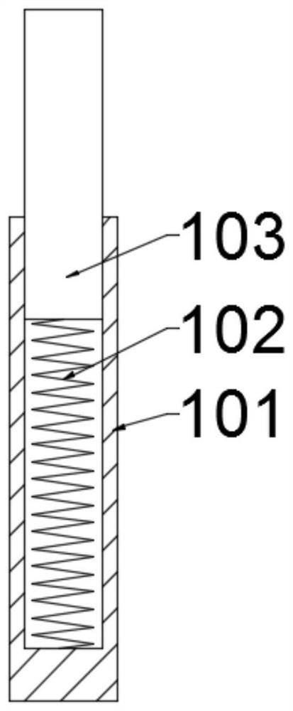
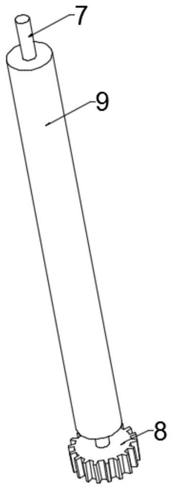
[0023] Example 1: Please refer to Figure 1-4 , a shock-absorbing support device for transporting a fan, including a support box 1, and several groups of fixed limit devices 2 are fixedly arranged on the inner side of the support box 1, and the fixed limit devices 2 include threaded connections with the top wall of the support box 1. The drive screw 3 is fixedly connected with the electromagnet 4 at the bottom of the support box 1, the bottom of the drive screw 3 is rotatably connected with a rotatable connection seat 5, and the bottom of the rotatable connection seat 5 is rotatably connected with a drive rack 6, and the drive rack 6 is connected with the support box 1 bottom sliding connection, the left and right sides of the drive rack 6 are symmetrically provided with a gear shaft 7 that is rotationally connected with the front and rear side walls of the support box 1, and the outer side of the gear shaft 7 is fixedly connected with a transmission gear 8, and the transmissio...

Embodiment 2

[0035] Example 2: Please refer to Figure 1-4 , a shock-absorbing support device for transporting a fan, including a support box 1, and several groups of fixed limit devices 2 are fixedly arranged on the inner side of the support box 1, and the fixed limit devices 2 include threaded connections with the top wall of the support box 1. The drive screw 3 is fixedly connected with the electromagnet 4 at the bottom of the support box 1, the bottom of the drive screw 3 is rotatably connected with a rotatable connection seat 5, and the bottom of the rotatable connection seat 5 is rotatably connected with a drive rack 6, and the drive rack 6 is connected with the support box 1 bottom sliding connection, the left and right sides of the drive rack 6 are symmetrically provided with a gear shaft 7 that is rotationally connected with the front and rear side walls of the support box 1, and the outer side of the gear shaft 7 is fixedly connected with a transmission gear 8, and the transmissio...


PUM


Abstract

The invention discloses a damping supporting device for fan carrying, and relates to the field of fans. The damping supporting device comprises a supporting box body, and a plurality of sets of fixedlimiting devices are fixedly arranged on the inner side of the supporting box body. Each fixed limiting device comprises a driving screw in threaded connection with the top wall of the supporting boxbody and an electromagnet fixedly connected with the bottom of the supporting box body. The bottom of the driving screw is rotationally connected with a rotary connecting base, the bottom of the rotary connecting base is rotationally connected with a driving rack, and the driving rack is slidably connected with the bottom of the supporting box. Gear shafts rotationally connected with the front andrear side walls of the supporting box are symmetrically arranged on the left and right sides of the driving rack, and the outer sides of the gear shafts are fixedly connected with transmission gears.During use, the positions of magnetic attraction blocks on the left side and the right side are adjusted by rotating the driving screw, so that the fan is better fixed, and side slipping of the fan in the transportation process is avoided. Meanwhile, damping can be achieved through springs at the bottom, the probability that the fan is damaged in the carrying process is greatly avoided, and the transportation effect is good.

Description

technical field [0001] The invention relates to the field of fans, in particular to a shock-absorbing support device for transporting a fan. Background technique [0002] Axial flow fan is one of the main types of fans. It has a wide range of uses. It is the airflow in the same direction as the axis of the blade. For example, electric fans and air conditioner fans are axial flow fans. It is called "axial flow" because the gas flows parallel to the shaft of the fan. Axial flow fans are usually used in occasions with high flow requirements and low pressure requirements. Axial fans hold the position and move the air. The axial flow fan is mainly composed of the fan impeller and the casing. The structure is simple but the data requirements are very high. [0003] Fans often slip or overturn due to vibration and other reasons during transportation, which damages the fan. Although the traditional transportation device can fix the fan, the fixing process is relatively complicate...

Claims


Application Information

Patent Timeline
Patent Type & Authority Applications(China)
IPC IPC(8): B65D61/00B65D85/68B65D81/07
CPCB65D61/00B65D81/07B65D85/68
Inventor 梁佳
Owner 梁佳
Learn More