Power cabinet suspension mounting equipment
A technology for installing equipment and power cabinets, which is applied in the field of adjustable suspension devices for container handling, and can solve the problems of not being able to support the bottom of the container
- Summary
- Abstract
- Description
- Claims
- Application Information
AI Technical Summary
Problems solved by technology
Method used
Image
Examples
specific Embodiment approach 1
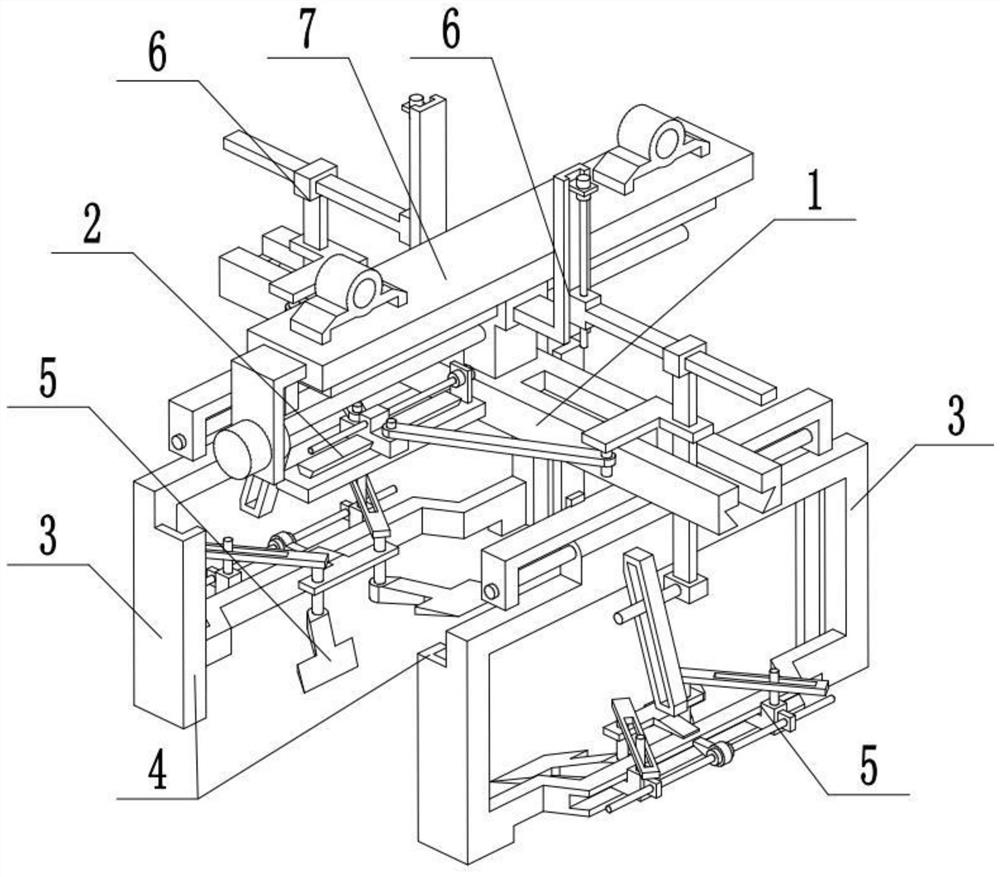
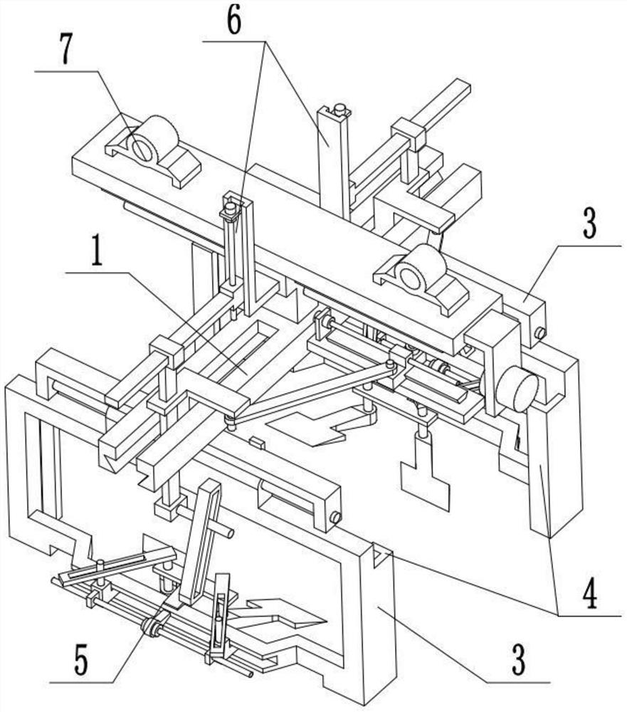
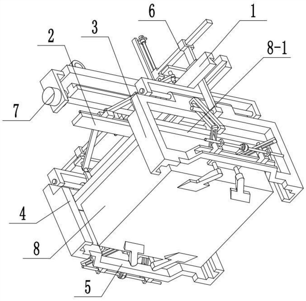
[0031] Combine below Figure 1-10Describe this embodiment, a power cabinet suspension installation equipment, including the I-shaped frame 1, the width adjustment member 2, the installation frame assembly 3, the L-shaped seat 4, the bottom support mechanism 5, the expansion adjustment member 6 and the container 8, the The width adjusting part 2 is fixedly connected to the I-shaped frame 1, and the two mounting frame components 3 are symmetrically slidably connected to the two ends of the I-shaped frame 1, and the two ends of the width adjusting part 2 are respectively connected with the two mounting frame components 3, and the two mounting frame components 3 are respectively connected. The two ends of the inner end surface of each mounting frame assembly 3 are respectively fixedly connected to an L-shaped seat 4, and two ribs 8-1 are symmetrically arranged on the container 8, and the two ribs 8-1 are respectively slidingly fitted and connected to two sides located on one side. ...
specific Embodiment approach 2
[0033] Combine below Figure 1-10 To illustrate this embodiment, the power cabinet suspension installation device also includes a position adjustment seat 7, which is connected to the work frame 1; the lower end of the work frame 1 is provided with a trapezoidal chute 1-1 , the two mounting bracket components 3 are respectively slidingly fitted and connected to the two ends of the trapezoidal chute 1-1, the upper end of the work frame 1 is fixedly connected to the T-shaped seat 1-2, and the two expansion adjustment parts 6 are symmetrically fixedly connected to the T-shaped seat At both ends of 1-2, the T-shaped seat 1-2 is cooperatingly connected with the position adjustment seat 7; When the two mounting frame assemblies 3 move down to find the position of the container 8, the position of the two mounting frame assemblies 3 can be fine-tuned through the position adjustment seat 7, so that the two mounting frame assemblies 3 can align more accurately and quickly. Accurate con...
specific Embodiment approach 3
[0035] Combine below Figure 1-10 To illustrate this embodiment, the width adjusting member 2 includes a bottom plate 2-1, a trapezoidal edge 2-2, a sliding block 2-3, a first screw rod 2-4, a first motor 2-5 and an articulated arm 2-6; The bottom plate 2-1 is fixedly connected to the middle part of the I-shaped frame 1, the trapezoidal edge 2-2 is fixedly connected to the bottom plate 2-1, the sliding block 2-3 is slidingly fitted and connected to the trapezoidal edge 2-2, and the sliding block 2-3 is connected to the trapezoidal edge 2-2. The first screw rod 2-4 is connected through thread fit, the first screw rod 2-4 is connected on the output shaft of the first motor 2-5 through a coupling, and the first motor 2-5 is fixedly connected to the base plate 2-1 through the motor frame Above, the two ends of the sliding block 2-3 are rotatably connected to one articulated arm 2-6 respectively, and the two articulated arms 2-6 are matedly connected with the two installation frame...
PUM
 Abstract
Description
Claims
Application Information
 - R&D
- Intellectual Property
- Life Sciences
- Materials
- Tech Scout
- Unparalleled Data Quality
- Higher Quality Content
- 60% Fewer Hallucinations
Browse by: Latest US Patents, China's latest patents, Technical Efficacy Thesaurus, Application Domain, Technology Topic, Popular Technical Reports.
© 2025 PatSnap. All rights reserved.Legal|Privacy policy|Modern Slavery Act Transparency Statement|Sitemap|About US| Contact US: help@patsnap.com


