Gas turbine intake blowback control method, system and computer readable medium

A technology of gas turbine and control method, which is applied in the direction of gas turbine device, machine/engine, jet propulsion device, etc. It can solve the problems of affecting work efficiency, high cost of filter elements, and insufficient dryness of gas, and achieves stable data transmission, low blowback cost, Good blowback effect

Active Publication Date: 2021-07-20
管网集团(新疆)联合管道有限责任公司 +1
View PDF0 Cites 0 Cited by
  • Summary
  • Abstract
  • Description
  • Claims
  • Application Information

AI Technical Summary

Problems solved by technology

[0002] Gas turbines and aero-derivative engines need to extract air for combustion during operation. In order to prevent dust particles from entering the engine and damaging the blade equipment, an air filter is usually installed at the intake end. However, the air filter is used for a long time , Dust accumulates in the air inlet of the filter, causing the air inlet to be blocked, making the difference between the front and rear of the filter gradually increase, which affects the suction process. Therefore, after the dust accumulates to a certain amount, the filter element needs to be replaced. High and long cycle, need to shut down, seriously affect work efficiency, and the amount of replacement work is large
[0003] Under normal circumstances, the dust in the air is easier to deposit in the middle and lower part of the filter under the action of its own gravity and airflow field, and gradually increases from top to bottom, but the existing back blowing device is usually evenly distributed, and simultaneously Back blowing results in an unsatisfactory back blowing effect and a waste of resources. On the one hand, the traditional back blowing system can only set a fixed time for blowing air, which lacks flexibility and cannot achieve the best back blowing effect; on the other hand On the one hand, the gas used for back blowing usually uses ordinary gas compressed by a compressor. The gas is not dry enough, and it is easy to wet the dust dropped by back blowing on the air filter element and re-adsorb on the air filter

Method used


Image

  • Gas turbine intake blowback control method, system and computer readable medium
  • Gas turbine intake blowback control method, system and computer readable medium
  • Gas turbine intake blowback control method, system and computer readable medium

Examples


Embodiment Construction

[0039] In the following description, specific details such as specific system structures and technologies are presented for the purpose of illustration rather than limitation, so as to thoroughly understand the embodiments of the present invention. It will be apparent, however, to one skilled in the art that the invention may be practiced in other embodiments without these specific details. In other instances, detailed descriptions of well-known systems, devices, circuits, and methods are omitted so as not to obscure the description of the present invention with unnecessary detail.

[0040] In order to illustrate the technical solutions of the present invention, specific examples are used below to illustrate.

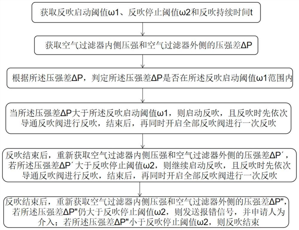
[0041] figure 1 It is a flow chart of a gas turbine intake blowback control method provided by an embodiment of the present invention. like figure 1 As shown, the gas turbine intake blowback control method of this embodiment includes the following:

[0042] Get the ...


PUM


Abstract

The invention discloses a gas turbine intake blowback control method, system and computer-readable medium. The gas turbine intake blowback control method includes: obtaining the blowback startup threshold ω 1 , Blowback stop threshold ω 2 and back-blowing duration t; obtain the pressure difference ΔP between the inside and outside of the air filter and determine whether the pressure difference ΔP is greater than the back-blowing start threshold ω 1 , when it is greater than , the blowback will be started, and when the blowback is performed, the blowback valves will be turned on one by one to carry out the blowback, and then all the blowback valves will be turned on at the same time for a blowback; the pressure difference ΔP′ will be obtained again, if it is greater than the blowback stop threshold ω 2 , repeat the backflushing of the above steps; after the backflushing is over, obtain the pressure difference ΔP″ again, if it is greater than the backflushing stop threshold ω 2 , send an error signal, and the applicant will intervene; if it is less than the blowback stop threshold ω 2 , the blowback ends. The present invention can achieve a better back blowing effect on the gas turbine filter by adopting the method of coordinating two back blows, and the cost of back blowing is low.

Description

technical field [0001] The invention relates to the technical field of gas turbine equipment maintenance, in particular to a gas turbine intake blowback control method, system and computer readable medium. Background technique [0002] Gas turbines and aero-derivative engines need to extract air for combustion during operation. In order to prevent dust particles from entering the engine and damaging the blade equipment, an air filter is usually installed at the intake end. However, the air filter is used for a long time , Dust accumulates in the air inlet of the filter, causing the air inlet to be blocked, making the difference between the front and rear of the filter gradually increase, which affects the suction process. Therefore, after the dust accumulates to a certain amount, the filter element needs to be replaced. High and the cycle is long, it needs to be shut down, which seriously affects the work efficiency, and the replacement project is large. [0003] Under norm...

Claims


Application Information

Patent Timeline
Patent Type & Authority Patents(China)
IPC IPC(8): F02C7/055F02C7/052F02C7/00F02C7/057
CPCF02C7/00F02C7/052F02C7/055F02C7/057
Inventor 张平刘小龙李星星罗易洲吕思琦王辉王冠霖蔡兴龙魏国富王子聪张富渊杨晓东付华正李亚民徐福根李文军黄俊陈浦
Owner 管网集团(新疆)联合管道有限责任公司
Why Eureka
Try Eureka