
Pneumatic separation nut device

A pneumatic separation and nut technology, applied in the direction of nuts, screws, bolts, etc., can solve the problems of poor synchronization, short unlocking time, large impact, etc., and achieve the effect of small impact response, short unlocking time and good synchronization

Inactive Publication Date: 2020-11-17
北京凌空天行科技有限责任公司
View PDF7 Cites 0 Cited by
  • Summary
  • Abstract
  • Description
  • Claims
  • Application Information

AI Technical Summary

Problems solved by technology

Explosive separation nut uses high-pressure gas generated by the explosion of pyrotechnics to push the internal mechanism away to achieve the purpose of unlocking. It is characterized by short unlocking time and good synchronization, but it has the defects of large impact and non-reusable, and it will affect the environment. Pollution; the memory alloy separation nut uses the principle that the memory alloy will expand and contract when the temperature changes, thereby driving the locking mechanism to unlock. It is characterized by small impact, no pollution, reusable, etc., but it has long unlocking time and poor synchronization. Defects

Method used


Image

  • Pneumatic separation nut device
  • Pneumatic separation nut device

Examples


Embodiment 1

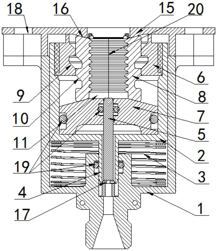
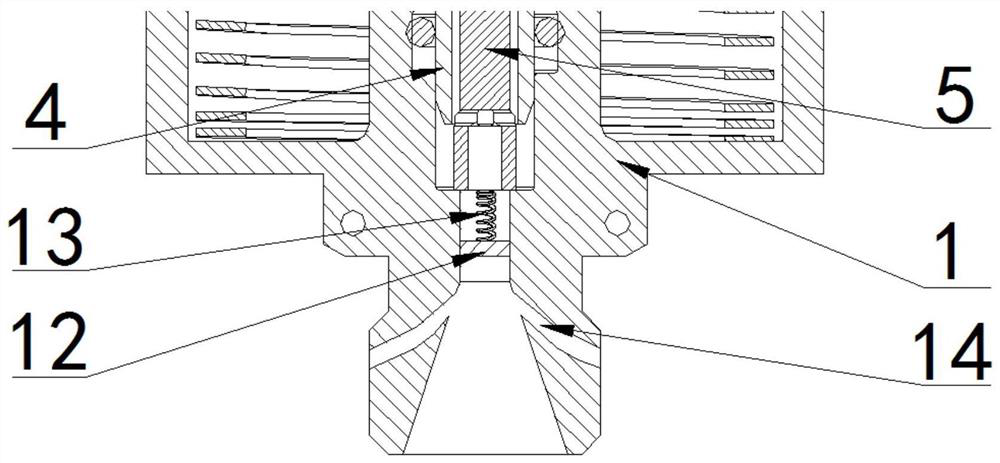
[0025] A pneumatic separation nut device, comprising: an outer shell 1 with a hollow interior, an inner cavity 2 arranged inside the outer shell, a separation assembly arranged inside the inner cavity 2 and a vertically arranged between the outer shell 1 and the inner cavity 2 The spring 3 between; the inner cavity 2 can slide up and down in the outer shell 1;

[0026] One end of the outer shell 1 is axially provided with a first through hole communicating with the outside, and one end of the inner cavity 2 is provided with an air inlet 4 extending axially, and the air inlet 4 penetrates the first A through hole; the air inlet portion 4 is provided with a second through hole communicating with the interior of the inner cavity 2, and the second through hole communicates with the first through hole; the air inlet portion 4 is axially provided There is a striker 5, one end of the striker 5 extends into the inner cavity 2, and the other end extends out of the air inlet 4, and the ...


PUM


Abstract

The invention discloses a pneumatic separation nut device. The pneumatic separation nut device comprises an outer shell body with a hollow interior, an inner cavity body formed in the outer shell body, a separation assembly arranged in the inner cavity body, and a spring vertically arranged between the outer shell body and the inner cavity body, wherein the inner cavity body is capable of slidingup and down in the outer shell body; one end of the outer shell body is axially provided with a first through hole which communicates with the outside, one end of the inner cavity body is provided with an air inlet part which extends in the axial direction of the inner cavity body, and the air inlet part penetrates into the first through hole; a striker is axially arranged in the air inlet part, one end of the striker stretches into the inner cavity, the other end of the striker stretches out of the air inlet part, and the inner wall of the first through hole is capable of limiting the position of the striker; and the separation assembly comprises a hoop connected with the end, away from the air inlet part, of the inner cavity body, a conical plug arranged at the end, away from the hoop, in the inner cavity, and a melon petal nut arranged between the conical plug and the inner wall of the inner cavity body in the axial direction. The device is small in impact response, capable of beingrepeatedly used, free of pollution to the environment, short in unlocking time and high in synchronicity.

Description

technical field [0001] The present disclosure generally relates to the technical field of separation nuts, in particular to a pneumatic separation nut device. Background technique [0002] Spacecraft such as satellites and test vehicles are launched into space by rockets, and they need to be separated from the satellite and the rocket. In addition, after the rocket is launched, multiple separations are required, such as separation between stages, booster separation, fairing separation, etc. , so the separation device occupies an important position in the aerospace field. The more commonly used separation devices include explosive bolts, explosive nuts, satellite separation rings, etc., and the separation devices are almost always explosives for unlocking. [0003] In the prior art, two common forms of separation nuts are explosion separation nuts and memory alloy separation nuts. Explosive separation nut uses high-pressure gas generated by the explosion of pyrotechnics to p...

Claims


Application Information

Patent Timeline
IPC IPC(8): F16B39/34F16B39/36F16B39/22F16B37/00
CPCF16B37/00F16B39/22F16B39/34F16B39/36
Inventor 不公告发明人
Owner 北京凌空天行科技有限责任公司
Learn More