A split memory alloy spring pin
What is Al technical title?
Al technical title is built by PatSnap Al team. It summarizes the technical point description of the patent document.
A memory alloy spring and memory alloy technology, applied in bolts and other directions, can solve the problems of limited bearing capacity of the pin puller, large unlocking impact, small locking force, etc., and achieve the effects of less cooling time, short unlocking time and compact structure.
Active Publication Date: 2022-04-08
AEROSPACE DONGFANGHONG SATELLITE
View PDF5 Cites 0 Cited by
Summary
Abstract
Description
Claims
Application Information
AI Technical Summary
This helps you quickly interpret patents by identifying the three key elements:
Problems solved by technology
Method used
Benefits of technology
Problems solved by technology
Traditional pin pullers generally use pyrotechnic pin pullers, which have the problem of excessive unlocking impact, and can only be used once, and have gradually been replaced by non-pyrotechnic pin pullers with less impact (such as memory alloy pin pullers, etc.)
However, most of the existing memory alloy pin pullers directly provide the pin pulling force through the memory alloy. Due to the limitation of power consumption and material performance, the locking force that the memory alloy can provide is generally small, and the bearing capacity of the pin puller is also low. therefore restricted
In addition, after the memory alloy is heated by electricity, it can only be reset after cooling down for the next test. Although it can be used repeatedly, it is not convenient for actual use, especially for ground tests.
Method used
Image
Click on the blue label to locate the original text in one second.
Reading with bidirectional positioning of images and text.
Examples
Embodiment Construction
[0030] The present invention will be further described below in conjunction with accompanying drawing.
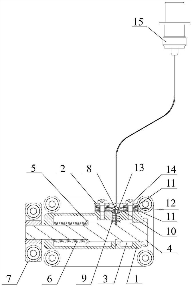
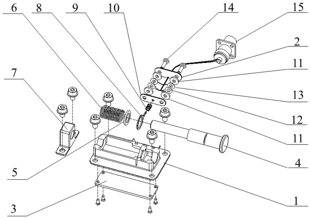
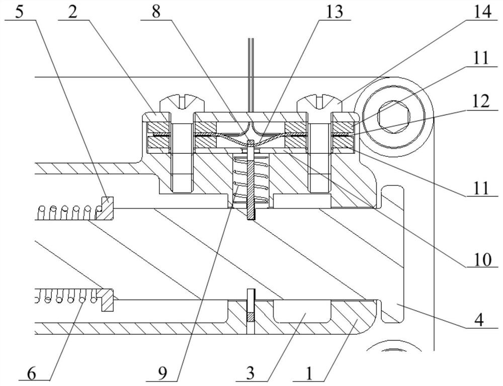
[0031] A split memory alloy spring pin, such as Figure 1-4 As shown, it includes mounting seat 1, side cover 2, bottom cover 3, pin 4, retaining ring 5, pin spring 6, pin hole seat 7, locking plate 8, locking spring 9, pressure plate 10, and insulation pad 11 , heating sheet 12, memory alloy sheet 13 and electrical connector 15, the side cover 2 is installed on the side of the mounting seat 1, and the bottom cover 3 is installed at the bottom;
[0032] The pin 4 passes through the round hole on the right wall of the mounting seat 1, the round hole in the middle rib, the locking plate 8, the retaining ring 5, the pin spring 6 and the round hole on the left side wall of the mounting seat 1 in sequence from the right, and finally inserts it into the pin hole seat 7 the pin hole;
[0033] One end of the locking piece 8 is a ring, the other end is a slender strip, the end of ...
PUM
Abstract
The invention provides a split-type memory alloy spring pin, which includes a mounting seat, a side cover, a bottom cover, a pin post, a retaining ring, a pin post spring, a pin hole seat, a locking plate, a locking spring, a pressing plate, an insulating heat insulation pad, a heating sheet, memory alloy sheet and electrical connector, the side cover is installed on the side of the mounting base, and the bottom cover is installed on the bottom; the pins pass through the round hole on the right side wall of the mounting base, the round hole of the middle rib, the locking plate, and the stopper in sequence from the right. ring, pin spring and the round hole on the left side wall, and finally inserted into the pin hole on the pin hole seat; one end of the locking plate is a ring, the other end is a slender strip, and the end of the slender strip is a hook, and the hook hook is The slender waist-shaped groove; the locking piece is inserted into the inner cylindrical hole through the narrow slit on the side of the mounting base, and the slender strip part passes through the lock spring and the pressure plate in turn, and finally hooks on the memory alloy piece. The spring pin of the present invention utilizes the principle that the memory alloy recovers the state before deformation after being heated, and realizes the remote control of unlocking the spring pin in combination with the electrical connector, and has the advantages of small size, low power consumption, easy operation and reusability.
Description
technical field [0001] The invention relates to a split-type memory alloy spring pin, which is especially suitable for unlocking micro-nano-satellite star-rocket separation mechanism, solar wing deployment unlocking, or satellite-borne antenna deployment unlocking for which the separation impact requirement is less than 100g, and can also be used for other low-impact unlocking Separate unlocking mechanism on demand. Background technique [0002] After the micro-nano satellite enters the orbit, it is necessary to release the locking of the satellite-rocket separation mechanism to the micro-nano satellite or antenna through the pin puller. After the spaceborne antenna enters the orbit with the satellite, it is necessary to release the locking of the antenna deployment mechanism to the antenna through the pin puller. Traditional pin pullers generally use pyrotechnic pin pullers, which have the problem of excessive unlocking impact, and can only be used once, and have gradually ...
Claims
Application Information
Patent Timeline
Application Date:The date an application was filed.
Publication Date:The date a patent or application was officially published.
First Publication Date:The earliest publication date of a patent with the same application number.
Issue Date:Publication date of the patent grant document.
PCT Entry Date:The Entry date of PCT National Phase.
Estimated Expiry Date:The statutory expiry date of a patent right according to the Patent Law, and it is the longest term of protection that the patent right can achieve without the termination of the patent right due to other reasons(Term extension factor has been taken into account ).
Invalid Date:Actual expiry date is based on effective date or publication date of legal transaction data of invalid patent.