High-precision pressure and flow measurement and control instrument

A high-precision, high-pressure technology, used in instruments, measuring fluid pressure, measuring flow/mass flow, etc., can solve the problem of reducing the connection firmness of the first installation pipe and the second installation pipe, the lack of limit of the installation sleeve, and the easy installation of the sleeve. Rotation and other problems to achieve the effect of improving connection firmness, improving connection sealing, and avoiding self-loosening

Active Publication Date: 2020-11-17
上海光键半导体设备有限公司
View PDF9 Cites 0 Cited by
  • Summary
  • Abstract
  • Description
  • Claims
  • Application Information

AI Technical Summary

Problems solved by technology

[0003] The purpose of the present invention is to provide a high-precision pressure and flow measurement and control instrument to solve the problem that the installation sleeve in the existing measurement and control instrument lacks a limit position in the above-mentioned background technology, and the installation sleeve is easy to rotate under the action of an external force, thereby reducing the The problem of the firmness of the connection between the first installation pipe and the second installation pipe

Method used


Image

  • High-precision pressure and flow measurement and control instrument
  • High-precision pressure and flow measurement and control instrument
  • High-precision pressure and flow measurement and control instrument

Examples


Embodiment Construction

[0024] The following will clearly and completely describe the technical solutions in the embodiments of the present invention with reference to the accompanying drawings in the embodiments of the present invention. Obviously, the described embodiments are only some, not all, embodiments of the present invention. Based on the embodiments of the present invention, all other embodiments obtained by persons of ordinary skill in the art without making creative efforts belong to the protection scope of the present invention.

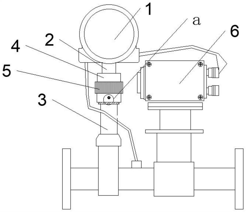
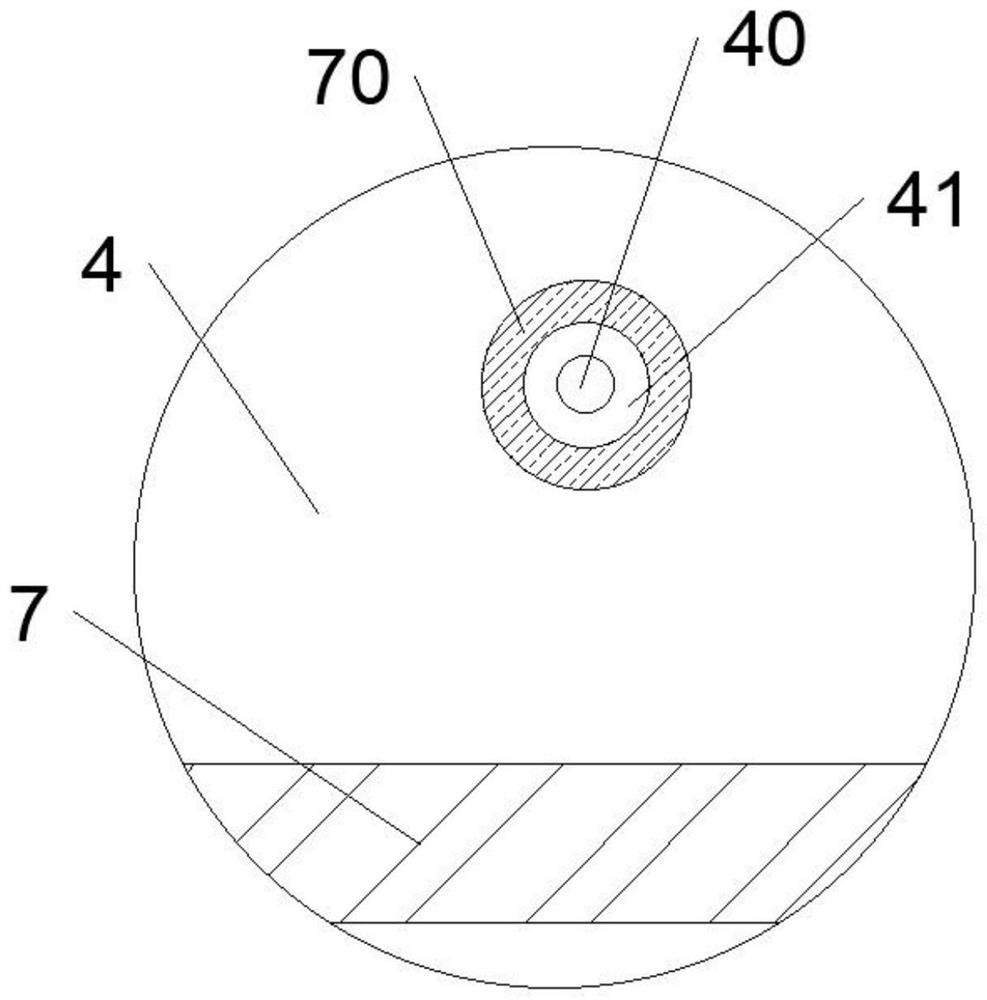
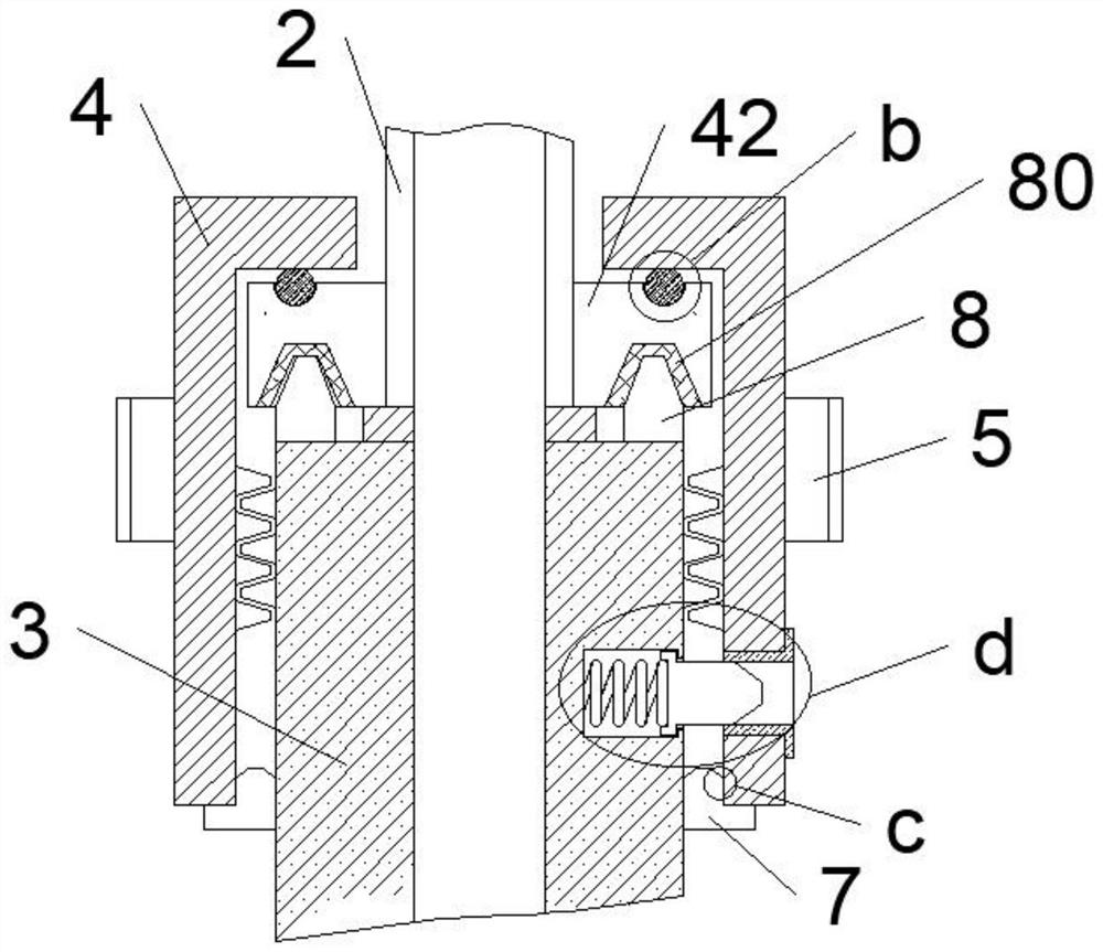
[0025] see Figure 1-Figure 6 , the present invention provides a technical solution: a high-precision pressure and flow measurement and control instrument, including a flow pressure converter 1, the bottom end of the flow pressure converter 1 is fixedly connected with a first installation pipe 2, and the bottom end of the first installation pipe 2 The second installation pipe 3 is provided, and the bottom end of the first installation pipe 2 is fixedly pierced...


PUM


Abstract

The invention discloses a high-precision pressure and flow measurement and control instrument which comprises a flow pressure converter, the bottom end of the flow pressure converter is fixedly connected with a first mounting pipe, the bottom end of the first mounting pipe is provided with a second mounting pipe, and the bottom end of the first mounting pipe is fixedly provided with a reinforcingring in a penetrating mode. A mounting sleeve is arranged on the outer side of the joint of the reinforcing ring and the second mounting pipe, a limiting groove is formed in the outer side of the mounting sleeve, an inward mounting groove is formed in the bottom end of the outer side of the second mounting pipe, a spring is arranged at one end in the mounting groove, a limiting column is arrangedat one end of the spring, and one end of the limiting column penetrates through the mounting groove; one end of the limiting column is located in the limiting groove, and the limiting column is clamped with the mounting sleeve through the limiting groove; by additionally arranging the mounting sleeve on the outer side of the joint of the second mounting pipe and the reinforcing ring, under the action of the limiting column and the limiting groove, the self-loosening situation of the mounting sleeve is effectively avoided, and the connecting firmness of the first mounting pipe and the second mounting pipe is further improved.

Description

technical field [0001] The invention belongs to the technical field of measurement and control instruments, in particular to a pressure and flow measurement and control instrument with high precision. Background technique [0002] Flow measurement and control instruments are industrial automation instruments used to measure and control the flow and pressure of fluids such as liquids, gases or steam in pipelines or open channels, and are widely used in petroleum, chemical, metallurgy, electric power and light industry industries. In the existing measurement and control instruments, the installation sleeve lacks a limit, and the installation sleeve is easy to rotate under the action of external force, thereby reducing the problem of the connection between the first installation pipe and the second installation pipe. Therefore, we propose a high-precision Pressure and flow measurement and control instruments. Contents of the invention [0003] The purpose of the present inve...

Claims


Application Information

Patent Timeline
Patent Type & Authority Applications(China)
IPC IPC(8): G01L19/00G01F1/00G01D21/02
CPCG01L19/0092G01F1/00G01D21/02
Inventor 张承勇
Owner 上海光键半导体设备有限公司
Why Eureka
Try Eureka