Card edge connector

A technology of card edge connectors and card slots, applied in the direction of connection, fixing/insulating contact components, connecting parts, protective grounding/shielding devices, etc., to achieve the effect of improving high frequency and strengthening strength

Active Publication Date: 2020-11-17
重庆市鸿腾科技有限公司 +1
View PDF6 Cites 0 Cited by
  • Summary
  • Abstract
  • Description
  • Claims
  • Application Information

AI Technical Summary

Problems solved by technology

However, as the rate increases, the performance requirements for signal transmission are higher, and the above-mentioned DDR connectors cannot meet the requirements

Method used


Image

  • Card edge connector
  • Card edge connector
  • Card edge connector

Examples


Embodiment Construction

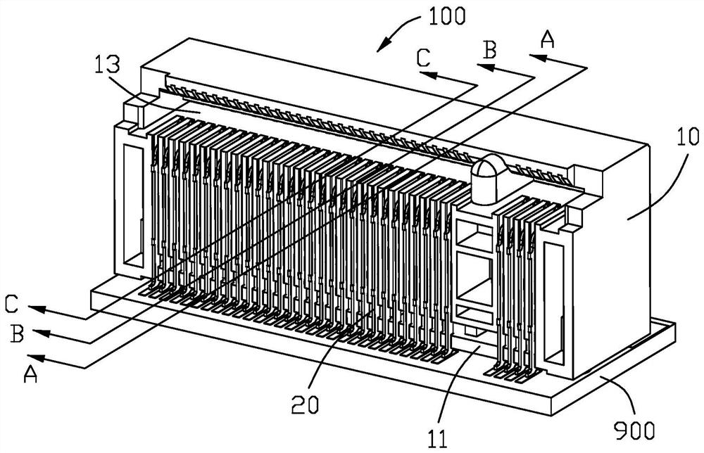
[0027] Figure 1 to Figure 6 The card edge connector of the present invention is shown, which is used for inserting an M.2 module or M.2 card that transmits PCI-EXPRESS signals, and the specific structure will be introduced in detail below.

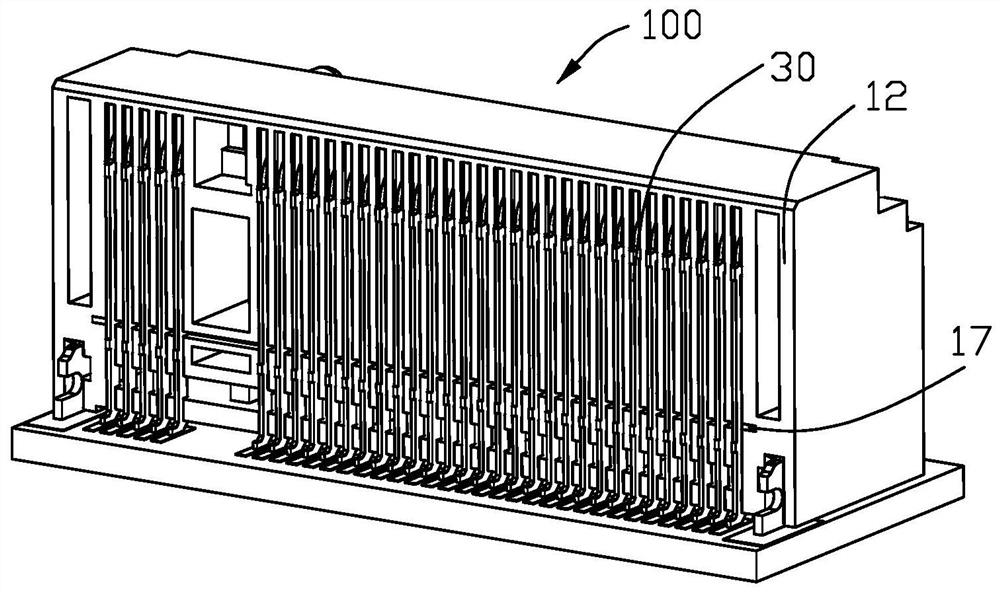
[0028] ginseng Figure 1-3 As shown, the card edge connector 100 includes an insulating body 10 , a row of first terminals 20 , a row of second terminals 30 and a grounding member 40 . The insulating body 10 includes opposite front surfaces 11 and rear surfaces 12 , and a slot 13 extending through the front surfaces 11 . combine Figure 4 It can be seen that the card slot 13 runs through forward, and the upper wall of the card slot is relatively short, located behind the lower wall, for oblique insertion of the electronic card.

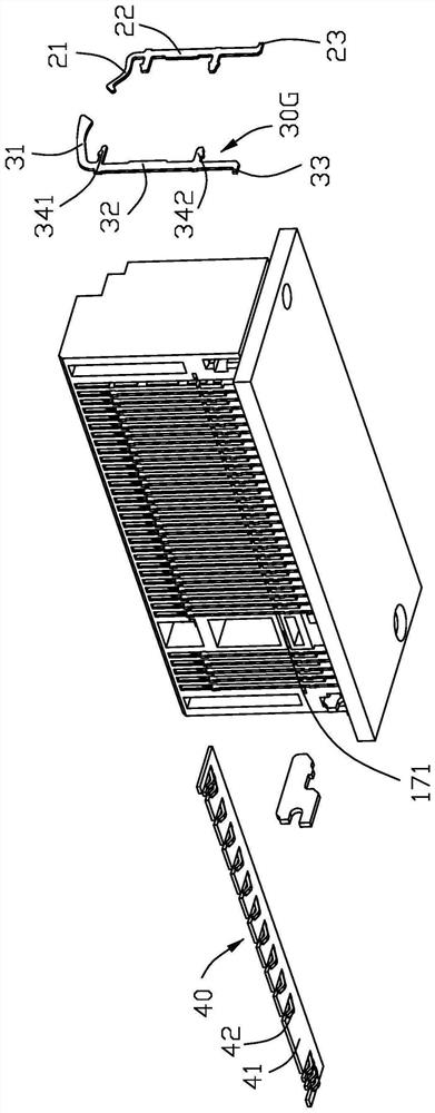
[0029] combine Figure 4 As shown, the first terminal 20 is inserted into the insulating body 10 backward from the front end face 11 . The first terminal 20 includes a fixing portion 22 , an elastic portion ...


PUM


Abstract

A card edge connector comprises an insulating body, a row of first terminals, a row of second terminals and a grounding piece, the insulating body comprises a front end face, a rear end face and a clamping groove penetrating through the front end face, the front end face and the rear end face are opposite to each other, and each of the first terminals and the second terminals comprises a fixing portion, an elastic portion extending from the fixing portion to the clamping groove and a pin. The elastic part is provided with a contact part protruding into the clamping groove, the fixing part of the first terminal is fixed to the position, close to the front end face, of the insulating body, and the fixing part of the second terminal is fixed to the position, close to the rear end face, of theinsulating body. The fixing part protrudes forwards from the front edge of the fixing part to form a first interference part and a second interference part, and the first interference part and the second interference part are fixed on the insulating body; the row of second terminals comprises signal terminals and grounding terminals, the grounding piece is provided with a plurality of grounding fingers, and the grounding fingers abut against the second interference parts of the corresponding grounding terminals. The grounding piece is positioned in the insulating body, so that high frequencycan be improved, and the strength of the connector is enhanced.

Description

【Technical field】 [0001] The invention relates to a card edge connector. 【Background technique】 [0002] Utility model patent No. CN210628555U discloses a DDR connector. Connector The connector includes a socket and brackets connected to both ends of the socket. A slot is provided in the socket, and a first terminal hole and a second terminal hole are respectively provided at both ends of the socket. The first terminal A first terminal is provided in the hole, a second terminal is provided in the second terminal hole, a first jack and a second jack are provided at one end of the bracket close to the socket, and the first jack is inserted A support plate is connected, the support plate is located directly below the bracket, the support plate includes a first plug-in portion plugged into the first socket, a pad connected to one end of the first plug-in portion The plate part, the support part connected to the lower side of the middle part of the backing part, the installatio...

Claims


Application Information

Patent Timeline
Patent Type & Authority Applications(China)
IPC IPC(8): H01R12/72H01R13/648H01R13/40
CPCH01R12/72H01R13/648H01R13/40
Inventor 赵志斌叶明坤余宏基
Owner 重庆市鸿腾科技有限公司
Why Eureka
Try Eureka