
Optical anti-shake camera module, camera anti-shake system and method and mobile terminal

A camera module and optical anti-shake technology, applied in the components of TV systems, image communication, TV, etc., can solve problems such as complex structure, loss of edge image quality, and large signal attenuation, so as to optimize the overall structure and reduce complexity degree, the effect of reducing the overall size

Pending Publication Date: 2020-11-17
重庆市天实精工科技有限公司
View PDF0 Cites 3 Cited by
  • Summary
  • Abstract
  • Description
  • Claims
  • Application Information

AI Technical Summary

Problems solved by technology

[0002] The traditional camera module without anti-shake function will cause the problem of unclear picture quality due to the shaking of the hand-held person when taking pictures
The anti-shake camera modules we can see at present usually achieve the purpose of anti-shake by moving the lens. This kind of anti-shake itself is easy to cause problems such as vignetting and loss of edge image quality. The anti-shake effect is limited, and the anti-shake correction range Not as good as the anti-shake module
In the existing module anti-shake solutions, due to the complex structure, large size, high cost, too long flexible board cable, and large signal attenuation, it is impossible to eliminate the pulling force of the flexible board on the camera module itself, and the applicability is relatively low. limitations

Method used


Image

  • Optical anti-shake camera module, camera anti-shake system and method and mobile terminal
  • Optical anti-shake camera module, camera anti-shake system and method and mobile terminal
  • Optical anti-shake camera module, camera anti-shake system and method and mobile terminal

Examples


Embodiment 1

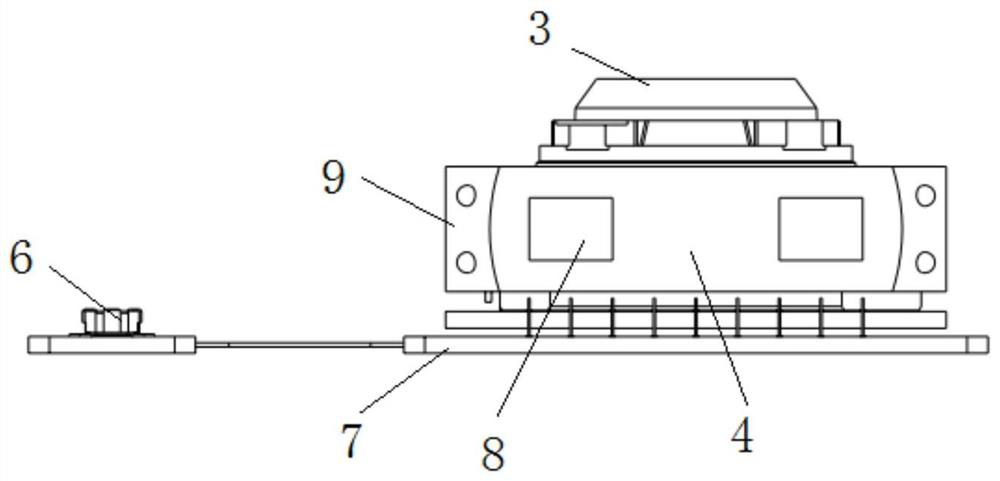
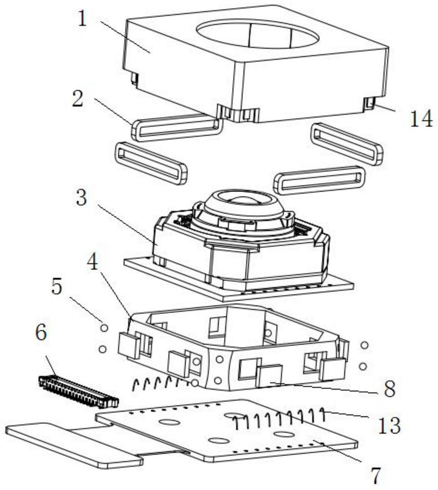
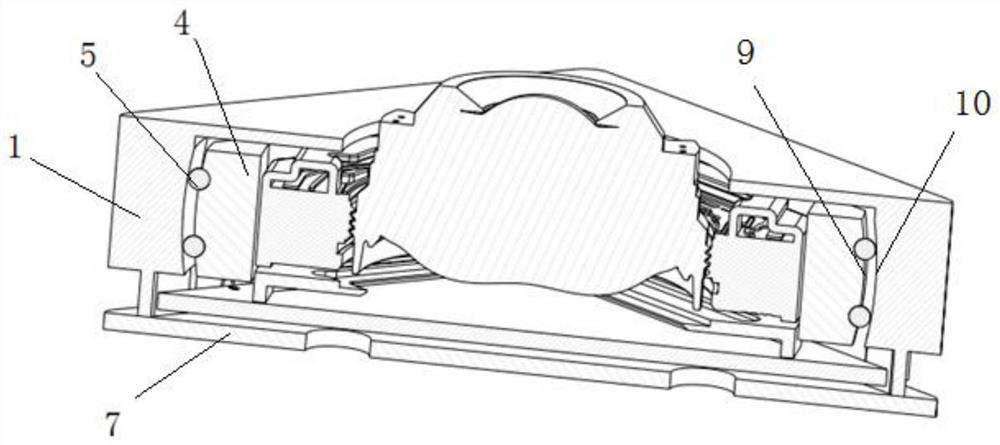
[0037] like Figure 1 to Figure 3 As shown, in this embodiment, an optical anti-shake camera module includes a camera module body 3 , a stator 1 , a rotor 4 and a bottom circuit board 7 .

[0038] like figure 2 and image 3 As shown, the rotor 4 is a square frame, and the outer surface of the connecting part of any two adjacent frames of the square frame is the first arc surface 9, and the four first arc surfaces 9 are all located on the same spherical surface. The rotor 4 is fixedly sleeved outside the camera module body 3 , and two first driving parts are provided on each surface of the rotor 4 . The lower end of the stator 1 is fixed on the bottom circuit board 7 , and the stator 1 is covered outside the rotor 4 . The inner side of the stator 1 is provided with a second arc surface 10 at a position corresponding to each of the first arc surfaces 9 , and the four second arc surfaces 10 are all located on the same spherical surface. A ball groove is opened on the first a...

Embodiment 2

[0054] In this embodiment, a first driving member is provided on two adjacent frames of the rotor 4 .

[0055] All the other parts are the same as the first embodiment.

Embodiment 3

[0057] In this embodiment, a first driving member is provided on each of the four frames of the rotor 4 .

[0058] All the other parts are the same as the first embodiment.


PUM


Abstract

The invention discloses an optical anti-shake camera module, a camera anti-shake system, a camera anti-shake method and a mobile terminal. The optical anti-shake camera module comprises a camera module body, a stator, a rotor and a bottom plate circuit board, the connecting part of any two adjacent frames of the rotor is a first arc surface, and the four first arc surfaces are located on the samespherical surface; wherein the rotor is fixedly sleeved outside the camera module body, and at least two adjacent frames of the rotor are respectively and fixedly provided with a first driving piece;the lower end of the stator is fixedly arranged on the bottom plate circuit board, and the stator covers the rotor; second arc surfaces are arranged at the positions, corresponding to the first arc surfaces, of the inner side surface of the stator, and the four second arc surfaces are located on the same spherical surface; a plurality of ball grooves are formed in the first arc surface of the rotor or / and the second arc surface of the stator, and balls are arranged in the ball grooves; and a second driving piece is arranged at the position, corresponding to the first driving piece, of the inner side of the stator. The optical anti-shake camera module has a photographing anti-shake function.

Description

technical field [0001] The invention belongs to the technical field of camera modules, and in particular relates to an optical anti-shake camera module, a camera anti-shake system, a method and a mobile terminal. Background technique [0002] The traditional camera module without anti-shake function will cause the problem of unclear picture quality due to the shaking of the hand-held person when taking pictures. The anti-shake camera modules we can see at present usually achieve the purpose of anti-shake by moving the lens. This kind of anti-shake itself is easy to cause problems such as vignetting and loss of edge image quality. The anti-shake effect is limited, and the anti-shake correction range Not as good as the anti-shake module. In the existing module anti-shake solutions, due to the complex structure, large size, high cost, too long flexible board cable, and large signal attenuation, it is impossible to eliminate the pulling force of the flexible board on the camera...

Claims


Application Information

Patent Timeline
IPC IPC(8): H04N5/225H04N5/232
CPCH04N23/50H04N23/54H04N23/6812H04N23/687
Inventor 秦攀登唐美罗卿卢江齐书苏黎东陈国狮
Owner 重庆市天实精工科技有限公司
Learn More