

Bean grinding processing device
A technology for grinding and processing beans, which is applied in the field of bean grinding and processing devices, can solve the problems of poor practicability and achieve the effect of convenient collection and control
- Summary
- Abstract
- Description
- Claims
- Application Information
AI Technical Summary
Problems solved by technology
Method used
Image

Examples
specific Embodiment approach 1
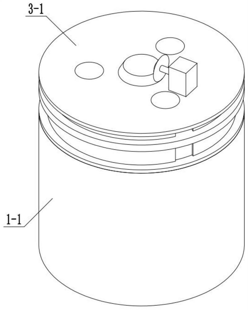
[0040] Combine below Figure 1-10 Describe this embodiment, a bean grinding and processing device, characterized in that it includes an outer casing 1-1, a plurality of bean drainage channels 1-2, a grinding surface 1-3, a grinding block 2-5, and a grinding column 2 -8. Grinding column push spring 2-9, drive assembly A, discharge sleeve 3-8 and inner end spring 4;
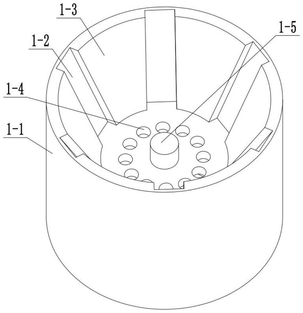
[0041] A plurality of bean drainage channels 1-2 are circumferentially arranged on the inner surface of the outer casing 1-1, and the grinding surface 1-3 is arranged on the inner surface of the outer casing 1-1;
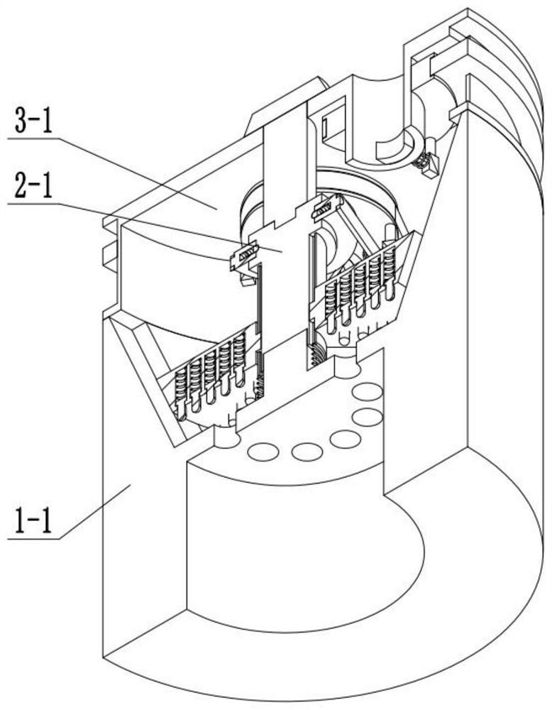
[0042] The grinding column 2-8 is slidingly connected with the grinding block 2-5, the grinding column push spring 2-9 is arranged on the inner end of the grinding column 2-8, and the grinding column push spring 2-9 is arranged on the grinding column 2-8 and the grinding block. Between 2-5,
[0043] The discharge casing 3-8 is fixedly connected with the drive assembly A;
[0044] The grinding block 2-...
specific Embodiment approach 2
[0047] Combine below Figure 1-10 Describe this embodiment, this embodiment will further explain Embodiment 1, and also includes a communication hole 1-4, an inner end rotating column 1-5 and a discharge chamber 1-6, and the communication hole 1-4 is set at the outer end casing 1- 1, the inner rotating column 1-5 is fixedly connected with the outer casing 1-1, the discharge chamber 1-6 is set at the lower end of the outer casing 1-1, and the communication hole 1-4 is connected with the discharge chamber 1-1. 6 is connected, and the inner end spring 4 is socketed and connected with the inner end rotating column 1-5.
specific Embodiment approach 3
[0049] Combine below Figure 1-10 Describe this embodiment, this embodiment will further explain the first embodiment, including the grinding main assembly A, the grinding main assembly A includes the driving column 2-1, the matching card slot 2-2, the driving column chute 2-7, the middle end matching Groove 2-10, grinding assembly A includes grinding block 2-5, grinding column 2-8, grinding column push spring 2-9, is arranged on the upper end of driving column 2-1 in cooperation with card slot 2-2, grinding block 2-5 Sliding fit connection with the drive column chute 2-7, the middle end matching groove 2-10 is arranged at the lower end of the drive column 2-1, and the drive column 2-1 connects with the inner end rotating column 1-5 through the middle end matching groove 2-10 Rotational connection, the inner end spring 4 is arranged between the outer end casing 1-1 and the driving column 2-1, the control assembly A is connected with the driving column 2-1, and the driving colu...
PUM
 Abstract
Description
Claims
Application Information