Kettle bottom cover mounting device

A technology for installing devices and kettles, applied in metal processing, metal processing equipment, manufacturing tools, etc.

Pending Publication Date: 2020-11-20
黄志建
View PDF5 Cites 7 Cited by
  • Summary
  • Abstract
  • Description
  • Claims
  • Application Information

AI Technical Summary

Problems solved by technology

[0004] Based on the above-mentioned problems existing in the installation of the bottom cover of the kettle, it is necessary to design a kettle bottom cover installation device that automatically places the kettle and the bottom cover and automatically pushes out the finished kettle to overcome the bottom of the above kettle. Disadvantages that the kettle body and bottom cover need to be manually placed on the pressing tool when the lid is installed, and the kettle needs to be picked up manually after installation

Method used


Image

  • Kettle bottom cover mounting device
  • Kettle bottom cover mounting device
  • Kettle bottom cover mounting device

Examples


Embodiment 1

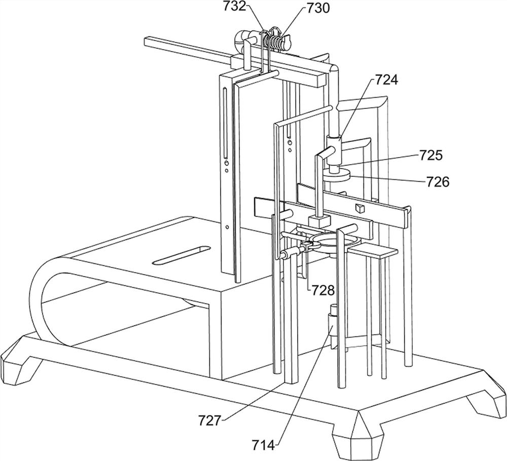
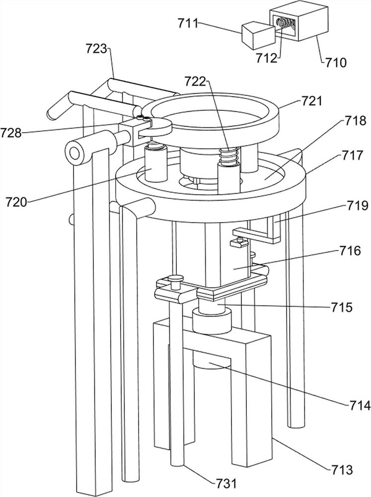
[0032] A kettle bottom cover installation device, such as Figure 1 to Figure 13 As shown, it includes a base 1, a support frame 2, a support rod 3, an installation rod 4, an electric push rod 5, a pressing mechanism 6 and a smoothing mechanism 7. The front and back of the side are symmetrically provided with support rods 3, and the top of the support frame 2 is symmetrically provided with mounting rods 4. The electric push rod 5 is provided with a pressing mechanism 6 on the top of the support frame 2, and the pressing mechanism 6 is connected with the support rod 3 and the electric push rod 5, and the right side of the top of the base 1 is provided with a smoothing mechanism 7, and the smoothing mechanism 7 is connected with the electric push rod 5 connections.

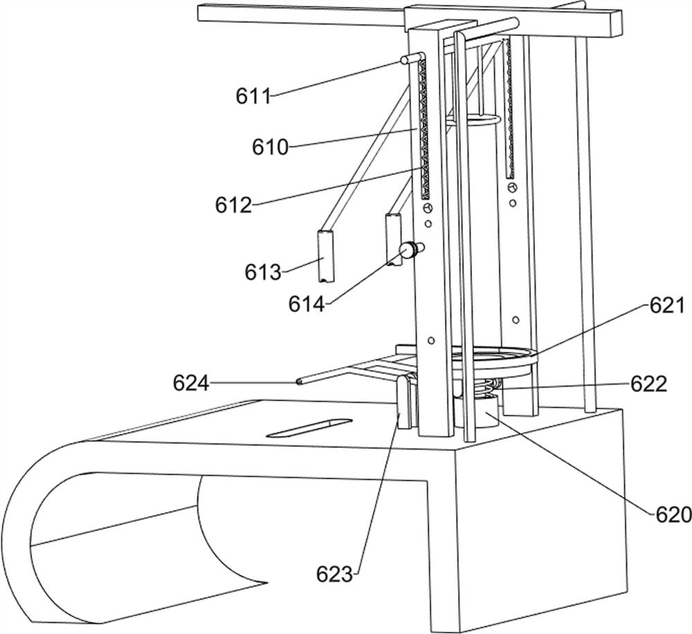
[0033] The pressing mechanism 6 includes a first slide rail 60, a spur rack 61, a fixed seat 62, a first winding wheel 63, a wedge-shaped sheave 64, a rotating disk 65, a drive shaft 66, a gear 67, a push rod 68, a...

Embodiment 2

[0037] On the basis of Example 1, such as Figure 11 to Figure 13 As shown, it also includes a chute frame 8, a push frame 9, a second sliding sleeve 10, a sliding block 11, a fifth spring 12, a mounting plate 13, a push rod 14, a third compression spring 15 and a second fixed frame 1501, The top of the support frame 2 is provided with a chute frame 8, grooves are arranged on the front and rear sides of the top of the chute frame 8, and a push frame 9 is slidably provided between the grooves on both sides, and the bottom of the push frame 9 is provided with a second sliding sleeve 10 , the second sliding sleeve 10 is slidingly provided with a sliding block 11, a fifth spring 12 is connected between the sliding block 11 and the second sliding sleeve 10, and a mounting plate 13 is arranged between the left middle parts of the support rods 3 on both sides. The middle part of the plate 13 is slidingly provided with a push rod 14, and a third compression spring 15 is connected betw...


PUM


Abstract

The invention relates to a bottom cover mounting device, and especially relates to a kettle bottom cover mounting device. The technical problem of the invention is to provide the kettle bottom cover mounting device that automatically places a kettle and a bottom cover and automatically pushes out the finished kettle. The kettle bottom cover mounting device comprises a base, a support frame, support rods, mounting rods and an electric push rod, and the support frame is arranged at one side of the top of the base; the support rods are longitudinally and symmetrically arranged at one side of thetop of the support frame; the mounting rods are longitudinally and symmetrically arranged at one side of the top of the support frame close to the support rods; and the electric push rod is arranged between the tops of the mounting rods and the tops of the support rods. The kettle bottom cover mounting device provided by the invention achieves the effect of automatically placing the kettle and thebottom cover and automatically pushing out the finished kettle, a plurality of bottom covers are manually placed in a second placing rack, a sliding block moves to the right to push a pushing frame to move to the right, the bottom covers are pushed to a placing tray, and the effect of automatically placing the bottom covers is achieved.

Description

technical field [0001] The invention relates to a bottom cover installation device, in particular to a kettle bottom cover installation device. Background technique [0002] The kettle body is made of stainless steel for boiling water. The stainless steel chassis heats up quickly, and the closed chassis heating design ensures that the water is completely boiled. The kettle body and the power base are separated for easy use. [0003] The bottom cover of the kettle is not integrated with the body of the kettle. When making a kettle, the kettle and the bottom cover need to be fitted together. Some manufacturers usually place the bottom cover At the bottom of a pressing tool, place the body of the kettle on the bottom cover, then open the pressing tool for preliminary installation of the kettle body and the bottom cover, and finally place the preliminarily installed kettle on the rotating worktable Rotate to smooth the bottom cover, so that the pot body and the bottom cover are...

Claims


Application Information

Patent Timeline
Patent Type & Authority Applications(China)
IPC IPC(8): B23P19/00
CPCB23P19/00B23P19/001B23P19/006
Inventor 黄志建
Owner 黄志建
Why Eureka
Try Eureka