
Feeding machine

A technology of feeding machine and feeding track, which is applied in the field of manufacturing capacitor shells and can solve problems such as inconvenience

Inactive Publication Date: 2015-11-11
ANHUI JIANGWEI PRECISION IND
View PDF8 Cites 2 Cited by
  • Summary
  • Abstract
  • Description
  • Claims
  • Application Information

AI Technical Summary

Problems solved by technology

[0004] The purpose of the present invention is to provide a feeder, which overcomes the inconvenient problem of manually placing raw materials in die-casting molds in the prior art, and realizes automatic placement and transportation of raw materials one by one

Method used


Image

  • Feeding machine

Examples


Embodiment Construction

[0021] Specific embodiments of the present invention will be described in detail below in conjunction with the accompanying drawings. It should be understood that the specific embodiments described here are only used to illustrate and explain the present invention, and are not intended to limit the present invention.

[0022] In the present invention, unless stated otherwise, the used orientation words such as "up, down, left, right" usually refer to figure 1 Up and down and left and right are shown. "Inner and outer" refer to the inner and outer on the specific outline. "Far and near" refer to far and near relative to a certain component.

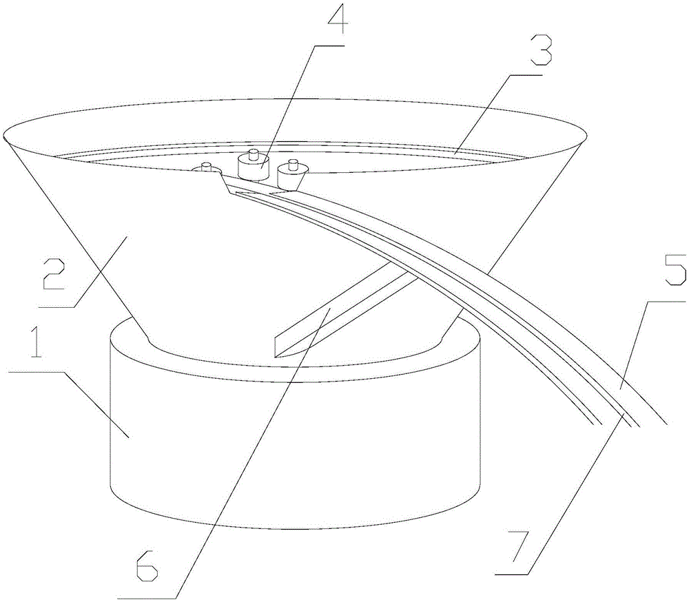
[0023] The present invention provides a feeder, which includes: a vibrating base 1, a material barrel 2, a spiral track 3, a runner 4 and a feeding track 5, the vibrating base 1 is arranged vertically below the material barrel 2, The spiral track 3 is arranged on the inner surface of the barrel 2, and one end port is arranged on the bot...


PUM


Abstract

The invention discloses a feeding machine. The feeding machine comprises a vibration base (1), a material barrel (2), a spiral rail (3), a plurality of rotating wheels (4) and a feeding rail (5), wherein the vibration base (1) is arranged under the material barrel (2) in the vertical direction; the spiral rail (3) is arranged on the inner surface of the material barrel (2); one opening in one end of the spiral rail (3) is formed in the bottom surface of the material barrel (2); one opening in the other end of the spiral rail (3) is communicated with the feeding opening of the feeding rail (5); the feeding rail (5) penetrates through the material barrel (2) and is fixedly connected to the outer surface of the material barrel (2); the rotating wheels (4) are arranged on one side of the spiral rail (3); the lateral sides of the rotating wheels (4) face the spiral rail (3), and the rotating wheels (4) can freely rotate in the axial direction. The feeding machine solves the problem that in the prior art, when raw materials are placed on a pressure casting mold through manual work, the operation is inconvenient, and realizes the operation that raw materials are automatically conveyed on by one.

Description

technical field [0001] The present invention relates to the field of manufacturing capacitor casings, in particular to a feeding machine. Background technique [0002] Capacitors, usually referred to as capacitance for their ability to hold charges, are denoted by the letter C. Definition 1: Capacitor, as the name suggests, is a "container for charging", a device that holds charges. English name: capacitor. Capacitors are one of the electronic components widely used in electronic equipment, and are widely used in DC blocking, coupling, bypass, filtering, tuning loops, energy conversion, control, etc. in circuits. Definition 2: Capacitor, any two conductors (including wires) that are insulated from each other and are very close to each other form a capacitor. [0003] In the production field of capacitors, transportation devices are required for the stamping of raw materials. In many cases, raw materials need to be transported one by one. In the prior art, the raw material...

Claims


Application Information

Patent Timeline
IPC IPC(8): B65G27/02B65G47/24
Inventor 林雪玉鲍启兵周池莲赵鑫万美云
Owner ANHUI JIANGWEI PRECISION IND
Learn More