
Hoisting equipment and hoisting control method

A technology for lifting equipment and hangers, which is applied in the direction of load hanging components, hoisting devices, transportation and packaging, etc., and can solve the problems of inconvenient regulation and control

Active Publication Date: 2020-11-20
SANY MARINE HEAVY IND
View PDF6 Cites 1 Cited by
  • Summary
  • Abstract
  • Description
  • Claims
  • Application Information

AI Technical Summary

Problems solved by technology

[0004] The purpose of this application is to provide a lifting device and a lifting control method, to a certain extent, to solve the technical problem of inconvenient regulation and control of the movement of the spreader in the prior art

Method used


Image

  • Hoisting equipment and hoisting control method
  • Hoisting equipment and hoisting control method
  • Hoisting equipment and hoisting control method

Examples


Embodiment 1

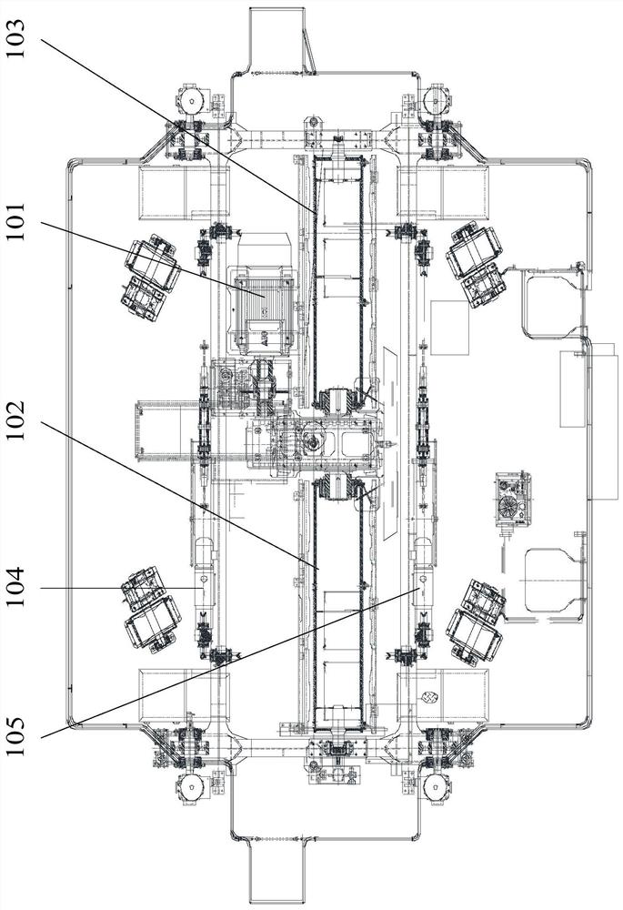
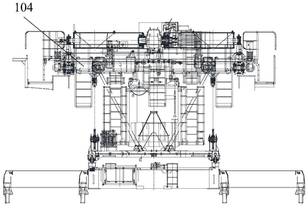
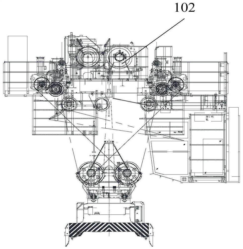
[0057] combine Figure 1-Figure 5 As shown, the present application provides a lifting device, including a hanger 140, a first drive assembly 101, a first reel 102, a second reel, a first push rod 104 and a second push rod 105;

[0058] The first driving assembly 101 can drive the first reel 102 and the second reel to rotate;

[0059] The hanger 140 is provided with two groups of first hanging joints, which are No. 1 first hanging joints and No. 2 first hanging joints; the No. 1 first hanging joints and the first hanging joints The No. 2 first hanging joint group is arranged at intervals along the width direction of the hanger 140;

[0060] The No. 1 first sling set includes two first slings, which are respectively the No. 1 first sling 108 and the No. 2 first sling. The No. 1 first sling 108 and the No. 1 first sling The No. 2 first slings are arranged at intervals along the length direction of the hanger 140; the No. 2 first sling group includes two first slings, respectiv...

Embodiment 2

[0094] The application also provides a lifting control method:

[0095] Step 100: Drive the first driving assembly, so that the first suspension rope 110 and the second suspension rope 111 are respectively wound on the first reel 102 and / or the third suspension rope and The fourth lifting rope is respectively released on the second drum; or the third lifting rope and the fourth lifting rope are respectively wound on the second drum and / or the first lifting rope 110 and the second suspension rope 111 are respectively released on the first reel 102 so that one or the other end of the hanger 140 in the length direction is tilted.

[0096] Step 200: drive the first push rod 104, the second push rod 105 is still, so that the hanger 140 rotates in the first direction or the second direction; drive the second push rod 105, the first A push rod 104 is stationary to rotate the hanger 140 in the third direction or the fourth direction.

[0097] Using the first driving assembly 101 to ...


PUM


Abstract

The invention relates to the technical field of cranes, and particularly relates to hoisting equipment and a hoisting control method. According to the hoisting equipment, two sets of first hoisting piece sets are arranged on a hanging bracket, and the two sets of first hoisting piece sets are arranged in the width direction of the hanging bracket at intervals; each set of first hanging piece set comprises two first hanging pieces, and the two first hanging pieces are arranged in the length direction of the hanging bracket at intervals, and a first winding drum is sequentially connected with one first hanging piece in one first hanging piece set and the telescopic end of a first push rod through a first hanging rope. By controlling the rotation directions of the first winding drum and a second winding drum through a first driving assembly, different hanging ropes are wound or released on the first winding drum and the second winding drum, tilting adjustment is achieved, a first push roddrives the first winding drum and the second winding drum, a second push rod drives the first winding drum and the second winding drum, rotation adjustment is achieved, adjustment is more convenient,and control is flexible.

Description

technical field [0001] The present application relates to the technical field of cranes for cargo transportation, and in particular to hoisting equipment and a hoisting control method. Background technique [0002] When transporting the spreader, a tire-type gantry crane is often used to translate, rotate and tilt the spreader. At present, the rotation of the spreader is realized by the anti-sway mechanism on the crane. It is realized by the diagonal point of the shelf, but the operation is complicated and inconvenient to control in this way. [0003] Therefore, there is an urgent need for a lifting device and a lifting control method to solve the problems in the prior art to a certain extent. Contents of the invention [0004] The purpose of this application is to provide a hoisting device and a hoisting control method, to a certain extent, to solve the technical problem of inconvenient regulation and control of the movement of the sling in the prior art. [0005] The p...

Claims


Application Information

Patent Timeline
Patent Type & Authority Applications(China)
IPC IPC(8): B66D1/12B66D1/14B66D1/28B66D1/26B66D1/36B66C13/06
CPCB66D1/12B66D1/14B66D1/28B66D1/26B66D1/36B66C13/06
Inventor 林汉华刘成才马士燕
Owner SANY MARINE HEAVY IND
Learn More