Project cost surveying and mapping equipment

A technology for engineering cost and equipment, applied in mechanical equipment, surveying and navigation, measuring devices, etc., can solve problems such as inability to adjust three-dimensional tilt, and achieve the effects of convenient observation, pollution prevention, and easy adjustment

Inactive Publication Date: 2021-10-01
李兆全
View PDF1 Cites 0 Cited by
  • Summary
  • Abstract
  • Description
  • Claims
  • Application Information

AI Technical Summary

Problems solved by technology

[0005] The purpose of the present invention is to independently rotate the two rotating blocks so that the surveying instrument can be tilted, which solves the problem that the traditional surveying instrument can only rotate and adjust the surveying instrument along one axis, and cannot adjust the three-dimensional tilt, which causes problems for the use of the surveying instrument. very limited problem

Method used


Image

  • Project cost surveying and mapping equipment
  • Project cost surveying and mapping equipment
  • Project cost surveying and mapping equipment

Examples


Embodiment 1

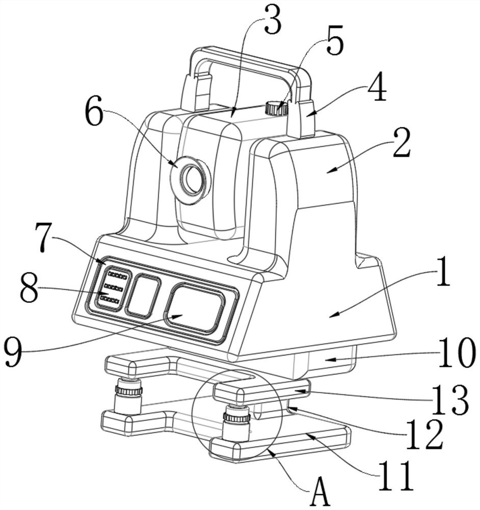
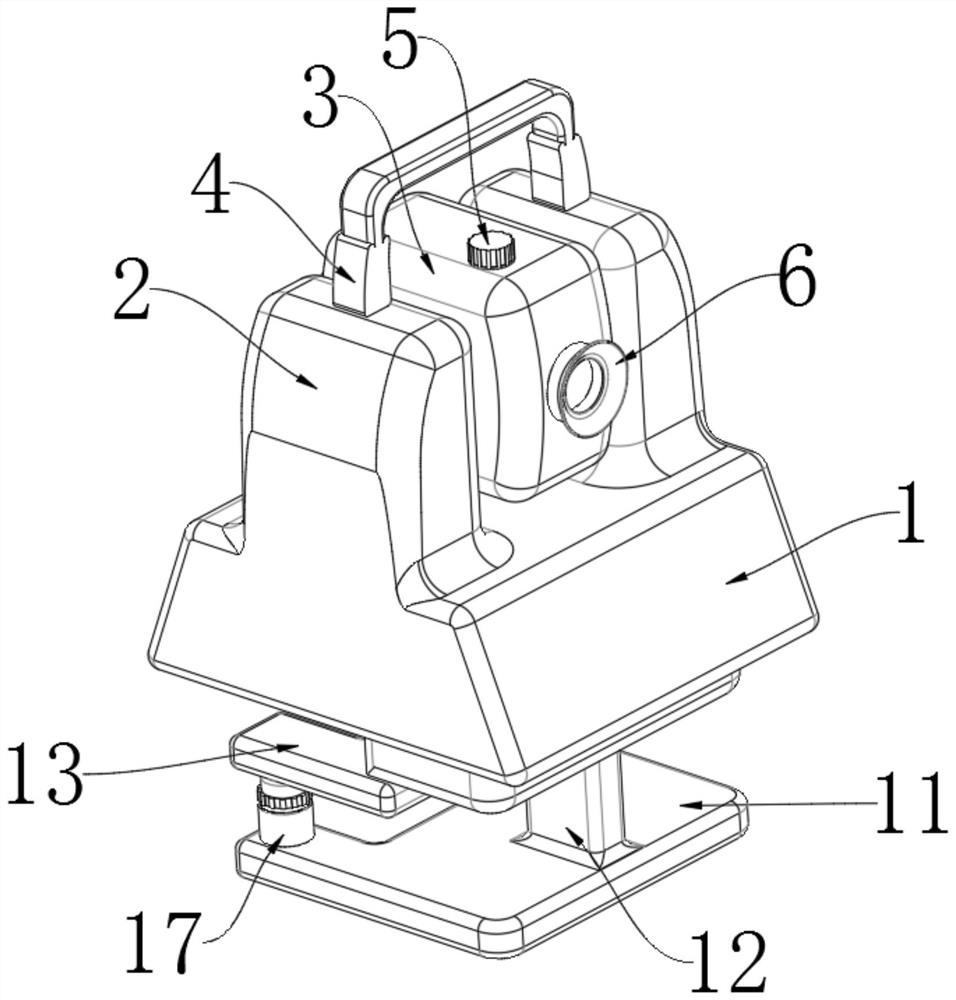
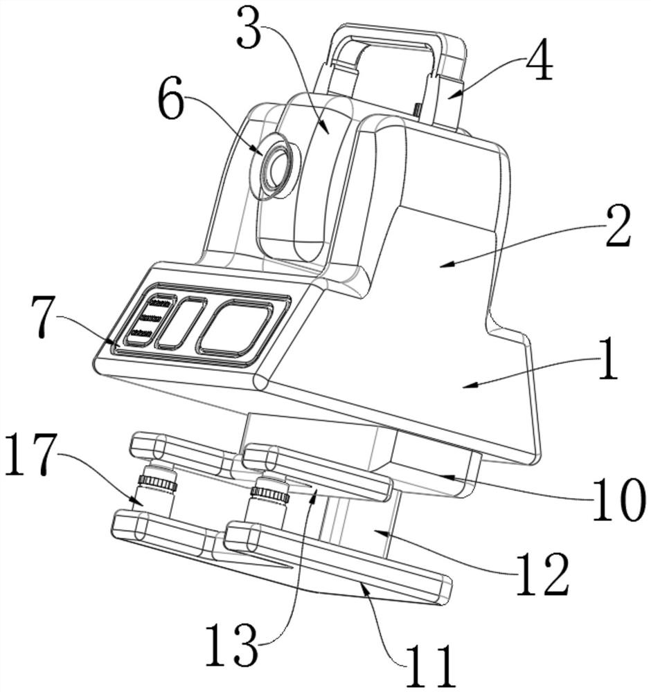
[0023] Example 1, such as Figure 1-4 As shown, the present invention provides a technical solution for engineering cost surveying and mapping equipment: including a base 1, a fixed block 10 is fixed at the bottom of the base 1 near one side edge, and a docking plate 13 is fixed at the bottom of the fixed block 10 near one side edge, The bottom of the docking plate 13 is fixed with a round head column 14 near two corners on one side, and the center of the bottom of the fixed block 10 is connected with a connecting block 12 through a universal joint, and the bottom of the connecting block 12 is fixed with a base plate 11. There are threaded columns 17 fixed at the two corners near the top of the top side, and the insides of the two threaded columns 17 are connected with rotating blocks 18 by threads, and the outer surfaces of the two rotating blocks 18 are fitted with non-slip rubber near the top edge. The top of the sleeve 16 and the two rotating blocks 18 are fixed with a con...

Embodiment 2

[0025] Example 2, such as Figure 1-4 As shown, the top of the base 1 is fixed with a support plate 2 close to the edge of the front surface and the rear surface, and the outer walls of one side of the two support plates 2 are connected with a surveying instrument 3 through bearing rotation, and one side of the base 1 is fixed with an adjustment The panel 7, the two round-head columns 14 and the corresponding concave blocks 15 are all coaxial, and the center of both sides of the surveying instrument 3 is fixed with a dust-proof ring 6, and the top of the surveying instrument 3 is rotated by a bearing near the edge of one side An adjustment knob 5 is connected, and a display panel 9 is fixed on the front surface of the adjustment panel 7 near the edge of one side. Both sides of the surveying instrument 3 are flush with both sides of the support plate 2. Two keypads 8 are fixed on the side edge, wherein one keypad 8 is located between one side of the other keypad 8 and one side ...


PUM


Abstract

The invention provides engineering cost surveying and mapping equipment, and relates to the technical field of surveying and mapping equipment. The equipment comprises a base, a fixing block is fixed to the position, close to the edge of one side, of the bottom of the base, a butt-joint plate is fixed to the position, close to the edge of one side, of the bottom of the fixing block, round-head columns are fixed to the two corners, close to one side, of the bottom of the butt-joint plate, a connecting block is rotationally connected to the center of the bottom of the fixing block through a universal joint, a bottom plate is fixed to the bottom of the connecting block, threaded columns are fixed to the two corners, close to one side, of the top of the bottom plate, rotating blocks are connected to the interiors of the two threaded columns through threads, and the outer surfaces of the two rotating blocks are fitted with non-slip rubber sleeves near the top edge. By independently rotating the two rotating blocks, the surveying and mapping instrument can incline, and the problems that a traditional surveying and mapping instrument can only be rotationally adjusted along one axis, three-dimensional inclination adjustment cannot be achieved, and great limitation is caused to the use of the surveying instrument are solved.

Description

technical field [0001] The invention relates to the technical field of surveying and mapping equipment, in particular to engineering cost surveying and mapping equipment. Background technique [0002] Simply speaking, surveying and mapping equipment is the instruments and devices designed for data collection, processing and output of surveying and mapping operations. Various instruments for orientation, distance measurement, angle measurement, height measurement, mapping and photogrammetry required for surveying in the planning, design, construction and operation management stages of engineering construction. [0003] In the prior art, as the Chinese patent number is: CN213021589U "a kind of engineering cost surveying and mapping equipment", it includes a base, and both sides of the top of the base are fixedly installed with installation rods, and the top of the base is located at A forward and reverse motor is fixedly installed between the installation rods, and a screw ro...

Claims


Application Information

Patent Timeline
Patent Type & Authority Applications(China)
IPC IPC(8): G01C15/00F16M11/18F16M11/06F16M11/04
CPCG01C15/00F16M11/06F16M11/043F16M11/18
Inventor 李兆全秦永胜
Owner 李兆全
Why Eureka
Try Eureka