Upper plate frame of photoetching machine

A technology of lithography machine and plate frame, which is applied in the direction of optomechanical equipment, microlithography exposure equipment, optics, etc., can solve the problems of low disassembly efficiency, difficult disassembly, rusty bolts and slipping wires, etc., and achieves simple operation Fast, reasonable structure, convenient operation, simple and fast effect

Inactive Publication Date: 2020-11-20
ADVANCED DIGITAL SCREEN SYST INC
View PDF6 Cites 0 Cited by
  • Summary
  • Abstract
  • Description
  • Claims
  • Application Information

AI Technical Summary

Problems solved by technology

[0003] The disadvantage of the above-mentioned patent is that it uses bolts to install the connecting plate, the efficiency of disassembly is low, and the bolts will ru

Method used


Image

  • Upper plate frame of photoetching machine
  • Upper plate frame of photoetching machine
  • Upper plate frame of photoetching machine

Examples


Example Embodiment

[0022] Below in conjunction with the accompanying drawings of the present invention in embodiments, the technical solutions in the embodiments of the present invention are clearly and completely described, obviously, the described embodiments are merely part of embodiments of the present invention rather than all embodiments.

[0023] In the description of the present invention, it is to be understood that the terms "upper", "lower", "front", "rear", "left", "right", "top", "bottom", "inner", " orientation or positional relationship of an outer "," front end "," rear "," ends "," end "," other end "or the like indicating a positional relationship of the orientation shown in the accompanying drawings, this is merely for convenience of description invention and simplicity of description, means or not indicate or imply element referred to must have a particular orientation, the orientation of a particular configuration and operation, can not be construed as limiting the present inven...


PUM


Abstract

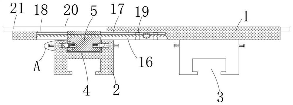
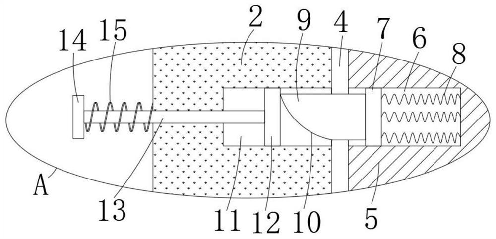
The invention discloses an upper plate frame of a photoetching machine. The upper plate frame comprises a connecting plate and two sliding blocks, and a limiting groove is formed in the bottom of theconnecting plate; two mounting blocks are connected into the limiting groove in a sliding manner; a transmission mechanism is arranged between the two mounting blocks and the limiting groove; and thetwo sliding blocks are each provided with a mounting groove. The two mounting blocks extend into the mounting grooves in the same side correspondingly. The two mounting grooves are each internally provided with two clamping grooves, the two clamping grooves are each internally provided with a pushing mechanism, clamping mechanisms are arranged between the two mounting blocks and the clamping grooves in the same side, the upper end of the connecting plate is provided with an extending groove, and the two extending grooves are each internally provided with an extending mechanism connected with the mounting block on the same side. The upper plate frame is reasonable in structure, capable of achieving rapid mounting and dismounting between the connecting plate and the sliding block, easy and rapid to operate, sufficient in stability, capable of adjusting the size of the plate face of the connecting plate, capable of conducting more stable supporting, capable of being suitable for differentrails and good in practicability.

Description

technical field [0001] The invention relates to the technical field of plate racks for lithography machines, in particular to plate racks for lithography machines. Background technique [0002] The prior art discloses a lithography machine upper frame with the application number CN201620426620.6, which includes: a base plate, at least two guide rails arranged in parallel on the top surface of the base plate, sliders slidably placed on the guide rails, The connecting plate that is detachably locked on the top surface of the slider, the raw material load-bearing platform that is detachably fixedly connected with the connecting plate, and the stopper that is set at one end of the guide rail to limit the travel range that the connecting plate moves with the slider The upper plate frame of the lithography machine includes at least two connecting plates for optional use, and the width of each connecting plate along the length direction of the guide rail is different. The upper fr...

Claims


Application Information

Patent Timeline
IPC IPC(8): G03F7/20
CPCG03F7/70741
Inventor 王群
Owner ADVANCED DIGITAL SCREEN SYST INC
Why Eureka
Try Eureka