
Fishpond underwater trap lamp with diffusion mirror

An insect trap lamp and diffuser mirror technology, which are applied in fish farming, agricultural fishing, and devices for catching or killing insects, etc. and other problems to achieve the effect of improving safety and convenience, and enhancing the effect of attracting insects.

Inactive Publication Date: 2020-11-24
扬州市宝迪照明科技有限公司
View PDF5 Cites 0 Cited by
  • Summary
  • Abstract
  • Description
  • Claims
  • Application Information

AI Technical Summary

Problems solved by technology

[0002] The black light insect trap lights currently used in fish ponds are generally above the water surface, and the black light tube emits light waves to attract insects to the surroundings, luring the pests to fly. However, most of the pests just fly around outside the insect baffle and cannot hit the insect baffle, so there are fewer pests falling into the water surface of the fish pond, so the number of pests that fish can eat is less
[0003] At present, the existing underwater insect traps for fish ponds with diffuser mirrors still have some shortcomings, for example; the existing underwater insect traps for fish ponds with diffuse mirrors cannot convert light energy or wind energy In order to store electrical energy in the battery and supply power to the entire circuit, it is necessary to connect power to the power supply to supply power to the fish pond underwater insect trap lamp, which reduces the safety and convenience of the fish pond underwater insect trap lamp power supply, and It is not possible to adjust the depth of the airtight insect trap lamp in the fish pond according to the water depth of the fish pond. The airtight insect trap lamp is prone to be too deep or too shallow in the fish pond, which weakens the insect trapping effect of the airtight insect trap lamp

Method used

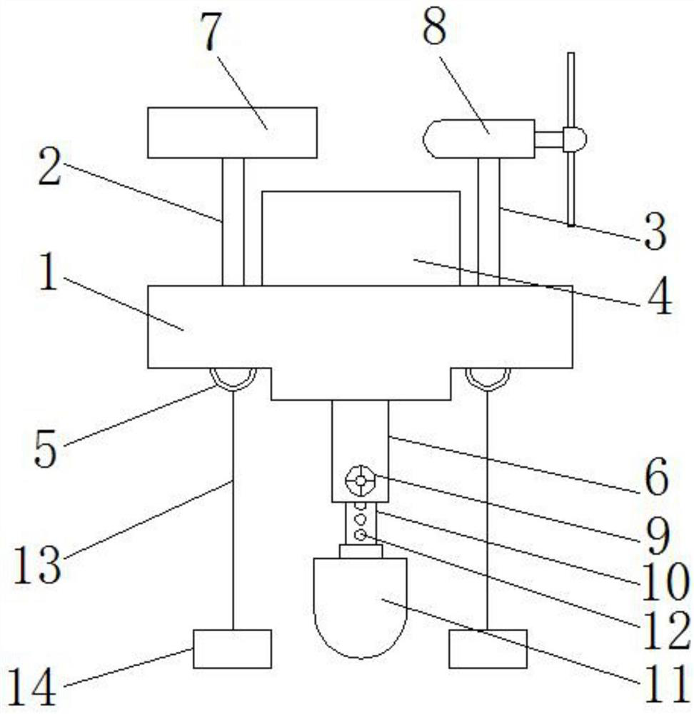

Image

  • Fishpond underwater trap lamp with diffusion mirror
  • Fishpond underwater trap lamp with diffusion mirror
  • Fishpond underwater trap lamp with diffusion mirror

Examples


Embodiment Construction

[0019] The following will clearly and completely describe the technical solutions in the embodiments of the present invention with reference to the accompanying drawings in the embodiments of the present invention. Obviously, the described embodiments are only some, not all, embodiments of the present invention.

[0020] In describing the present invention, it should be understood that the terms "upper", "lower", "front", "rear", "left", "right", "top", "bottom", "inner", " The orientation or positional relationship indicated by "outside", etc. is based on the orientation or positional relationship shown in the drawings, and is only for the convenience of describing the present invention and simplifying the description, rather than indicating or implying that the referred device or element must have a specific orientation, so as to Specific orientation configurations and operations, therefore, are not to be construed as limitations on the invention.

[0021] see Figure 1-Fig...


PUM


Abstract

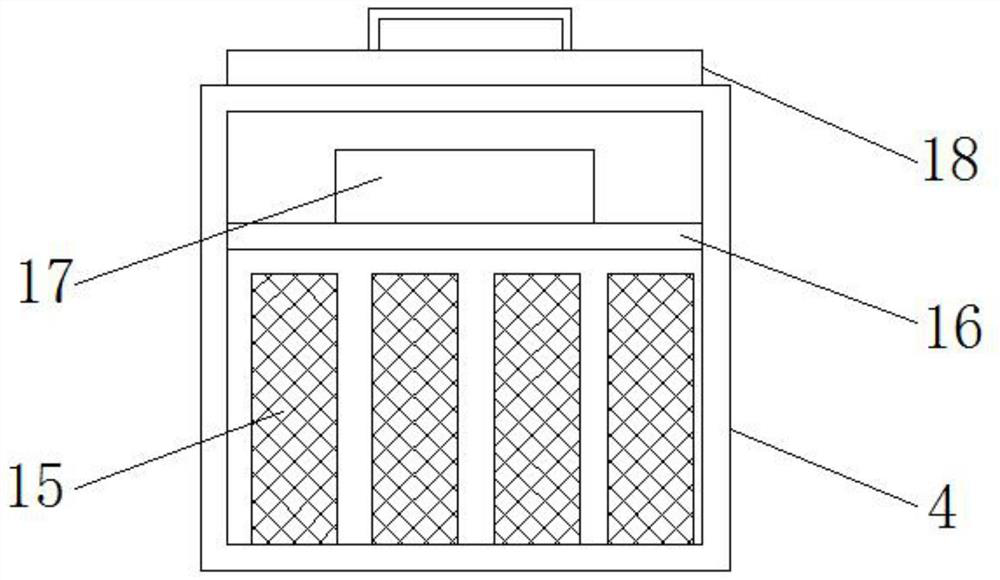
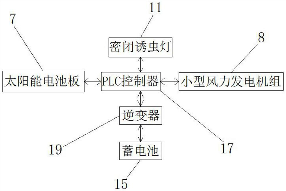
The invention discloses a Fishpond underwater trap lamp with a diffusion mirror. The fishpond underwater trap lamp structurally comprises a floating plate, wherein a supporting rod I, a supporting rodII, a protection box, a fixing ring and a hollow pipe are arranged on the floating plate; the supporting rod I is fixedly connected with the left side of the upper surface of the floating plate through screws, and the supporting rod II is fixedly connected with the right side of the upper surface of the floating plate through screws; and the protection box is fixedly connected with the middle ofthe upper surface of the floating plate through screws. Light energy or wind energy can be converted into electric energy to be stored in a storage battery, power is supplied to a whole circuit, it isavoided that a power supply is powered on to supply power to the fishpond underwater trap lamp, and the safety and convenience of power supply of the fishpond underwater trap lamp are improved; the depth of the closed trap lamp in the fishpond can be adjusted according to the water depth of the fishpond, the phenomenon that the depth of the closed trap lamp in the fishpond is too large or too small is avoided, and the insect trapping effect of the closed trap lamp is enhanced.

Description

technical field [0001] The invention relates to the technical field of insect trap lamps, in particular to an underwater insect trap lamp for fish ponds with a diffuser mirror. Background technique [0002] The black light insect trap lights currently used in fish ponds are generally above the water surface, and the black light tube emits light waves to attract insects to the surroundings, luring the pests to fly. However, most of the pests just fly around outside the insect barrier and cannot hit the insect barrier, so there are fewer pests falling into the water surface of the fish pond, so the number of pests that fish can eat is less. [0003] At present, the existing underwater insect traps for fish ponds with diffuser mirrors still have some shortcomings, for example; the existing underwater insect traps for fish ponds with diffuse mirrors cannot convert light energy or wind energy In order to store electrical energy in the battery and supply power to the entire circu...

Claims


Application Information

Patent Timeline
Patent Type & Authority Applications(China)
IPC IPC(8): A01M1/04A01K61/80
CPCA01M1/04A01K61/80Y02P60/60Y02A40/81
Inventor 胡官宝
Owner 扬州市宝迪照明科技有限公司
Learn More