
Separator mounting structure of dust collector

A technology of installation structure and separator, applied in the direction of vacuum cleaner, suction filter, cleaning equipment, etc., can solve the problems of lack of elasticity at the connection, poor user experience, and hard card of the separator.

Pending Publication Date: 2020-11-24
SUZHOU CHUNJU ELECTRIC CO LTD
View PDF0 Cites 0 Cited by
  • Summary
  • Abstract
  • Description
  • Claims
  • Application Information

AI Technical Summary

Problems solved by technology

[0003] However, in the current dust cup structure, the installation of the separator is basically hard stuck in the dust cup, so the current separator installation structure has no elasticity at the connection, which causes the user to have trouble when taking out and installing the separator. The time is very tight and sometimes it is very loose, giving users a very bad experience

Method used


Image

  • Separator mounting structure of dust collector
  • Separator mounting structure of dust collector
  • Separator mounting structure of dust collector

Examples


Embodiment Construction

[0020] Exemplary embodiments of the present disclosure will be described in more detail below with reference to the accompanying drawings. Although exemplary embodiments of the present disclosure are shown in the drawings, it should be understood that the present disclosure may be embodied in various forms and should not be limited to the embodiments set forth herein. Rather, these embodiments are provided for more thorough understanding of the present disclosure and to fully convey the scope of the present disclosure to those skilled in the art.

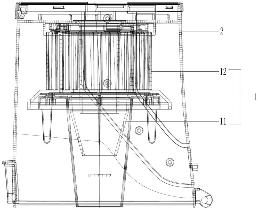
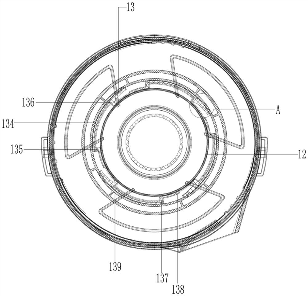
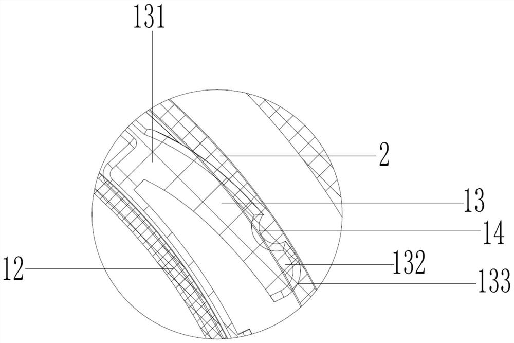
[0021] see Figure 1 to Figure 3 , the figure shows a separator installation structure of a vacuum cleaner provided by an embodiment of the present invention, which includes a separator assembly 1 installed in a dust cup 2, and the separator assembly 1 includes a separator bracket 11 and a separator 12, The separator 12 is fixedly connected to the separator bracket 11, the separator 12 is a cylindrical separator, and the top of the...


PUM


Abstract

The invention provides a separator mounting structure of a dust collector. The separator mounting structure comprises a separator assembly, which is mounted in a dust cup; the separator assembly comprises a separator support and a separator, the separator is fixedly connected to the separator support and is a cylindrical separator, a plurality of buckles are arranged at the top of the separator, the first ends of the buckles are tangent to the outer wall of the separator, the opposite second ends of the buckles extend outwards to form clamping ends, and the clamping ends are clamped to the inner wall of the dust cup. Compared with the prior art, the problem of tightness during disassembly and assembly of an existing separator can be effectively solved, and the user experience is improved.

Description

technical field [0001] The invention relates to the field of vacuum cleaners, in particular to a separator installation structure of a vacuum cleaner. Background technique [0002] When the dust bucket on the vacuum cleaner is sucking dust, the user needs to dump the garbage and clean up the clogged garbage wrapped around the separator, so the separator needs to be taken out for cleaning at this time. [0003] However, in the current dust cup structure, the installation of the separator is basically hard stuck in the dust cup, so the current separator installation structure has no elasticity at the connection, which causes the user to have trouble when taking out and installing the separator. The time is very tight and sometimes it is very loose, which gives users a very bad experience. Contents of the invention [0004] In view of this, the present invention provides a separator installation structure of a vacuum cleaner, which can effectively solve the tightness problem...

Claims


Application Information

Patent Timeline
IPC IPC(8): A47L9/10A47L9/00
CPCA47L9/00A47L9/102
Inventor 唐亚军
Owner SUZHOU CHUNJU ELECTRIC CO LTD
Learn More