Automobile bumper and bumper guard plate
A technology for automobile bumpers and bumpers, which is applied to bumpers, vehicle parts, and vehicle safety arrangements. Easy maintenance and replacement, quick disassembly and replacement, and convenient maintenance
- Summary
- Abstract
- Description
- Claims
- Application Information
AI Technical Summary
Problems solved by technology
Method used
Image
Examples
Embodiment 1
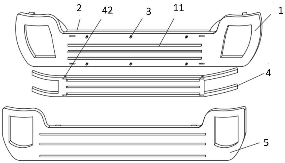
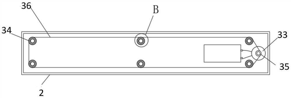
[0029] see Figure 1~5 , in an embodiment of the present invention, an automobile bumper includes a bumper body 1, a mounting shell 2 and a fastening mechanism 3, the mounting shell 2 is arranged on the side of the bumper body 1 close to the vehicle body, and the mounting A cavity structure is formed between the shell 2 and the bumper body 1;
[0030] The fastening mechanism 3 is arranged in the cavity structure, and the fastening mechanism 3 includes: a sleeve 311, a threaded rod 32, a drive motor 33, a first synchronous wheel 34, a second synchronous wheel 35 and a synchronous belt 36 , the threaded rod 32 is set in the casing 311, the drive motor 33 drives the second synchronous wheel 35 to rotate, and the second synchronous wheel 35 drives the first synchronous wheel through the synchronous belt 36 34 rotation, the rotation of the first synchronous wheel 34 drives the rotation of the sleeve 311, the sleeve 311 rotates synchronously with the threaded rod 32, the threaded r...
Embodiment 2
[0047] see figure 1 , figure 2 or Figure 6 , a bumper guard, including the automobile bumper in Embodiment 1 and the guard body 5, the guard body 5 is arranged on the side opposite to the bumper body 1 in the buffer member 4, the The inner wall of the shield body 5 is also provided with a positioning frame 51 and a threaded groove 52, one end of the auxiliary rod 322 is threadedly connected with the inner wall of the threaded groove 52, and the buffer member 4 is provided with a slot matching the positioning frame 51 42.
[0048] Specifically, the bumper guard further includes a locking mechanism 6 , and the locking mechanism 6 is installed in the installation hole 41 of the buffer member 4 .
[0049] Further, the locking mechanism 6 includes a locking block 61, a positioning piece 62 and a T-shaped tie rod 63, the locking block 61 is engaged with the positioning frame 51 of the guard body 5, and one end of the locking block 61 is connected to the The positioning piece 6...
PUM
 Abstract
Description
Claims
Application Information
 - R&D
- Intellectual Property
- Life Sciences
- Materials
- Tech Scout
- Unparalleled Data Quality
- Higher Quality Content
- 60% Fewer Hallucinations
Browse by: Latest US Patents, China's latest patents, Technical Efficacy Thesaurus, Application Domain, Technology Topic, Popular Technical Reports.
© 2025 PatSnap. All rights reserved.Legal|Privacy policy|Modern Slavery Act Transparency Statement|Sitemap|About US| Contact US: help@patsnap.com


