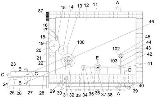
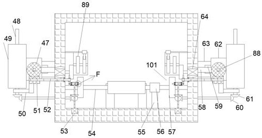
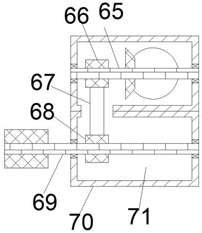
[0019] Combine below Figure 1-7 The present invention will be described in detail, in which, for the convenience of description, the following directions are specified as follows: figure 1 The vertical, horizontal, front and rear directions of the projection relationship are the same.
[0020] Attached Figure 1-7 The earthquake rescue equipment with life detection function includes a box body 11 and a first cavity 12 fixedly arranged in the box body 11. The outer surface of the left end wall of the box body 11 is fixedly installed with life In the detector 87, a sprocket shaft 31 is symmetrically mounted on the lower end wall of the first cavity 12 to rotate, and sprocket wheels 32 are fixedly mounted on the outer surfaces of the front and rear ends of the sprocket shaft 31. They are connected by a crawler belt 40. The outer surface of the end wall of the crawler belt 40 away from the sprocket 32 is fixedly arrayed with gripping blocks 39. The sprocket shaft 31 on the right side is dynamically connected to the main shaft of the first motor 80. , The first motor 80 is fixedly mounted on the lower end wall of the first cavity 12, and a second cavity 29 is fixedly provided on the left side of the lower end wall of the first cavity 12, and the second A first pulley 30 is fixedly mounted on the outer surface of the sprocket shaft 31 in the cavity 29, and the first pulley 30 and the second pulley 56 are connected by a first transmission belt 55, and the second pulley 56 is fixedly mounted on the outer surface of the gear shaft 54, which is rotatably mounted between the front and rear walls of the first cavity 12, and the left side of the first cavity 12 on the left side of the gear shaft 54 An opening 22 is fixedly provided on the end wall, and a first transmission device 100 for transmission between the gear shaft 54 and the wrecker 24 is installed on the outer surface of the gear shaft 54 on the front side of the second pulley 56. The outer surfaces of the front and rear ends of the gear shaft 54 are symmetrically installed with a second transmission device 101 for transmission between the gear shaft 54 and the lifting plate 26, and the right side of the lower end wall of the first cavity 12 is symmetrical in the front and rear. A rotating shaft 43 is rotatably installed, and the rotating shaft 43 is in power connection with the main shaft of the second motor 53, the second motor 53 is fixedly installed on the lower end wall of the first cavity 12, and the rotating shaft 43 is A third transmission device 102 for transmission between the rotating shaft 43 and the first screw rod 88 is installed on the outer surface of the side end. The first screw rod 88 is rotatably mounted on the first screw rod mounting plate 58, and the first screw rod The screw 88 is rotatably connected to the sliding plate 62. The sliding plate 62 is slidably mounted on the sliding plate mounting frame 63 through the sliding groove 59, and the sliding groove 59 is fixedly arranged on the sliding plate mounting frame 63 away from the box 11 On the end wall, the slide plate mounting frame 63 is symmetrically fixedly mounted on the front and rear walls of the box body 11, and the outer surface of the rotating shaft 43 on the lower side of the third transmission device 102 is installed for the rotating shaft 43 and The fourth transmission device 103 for transmission between the supporting plates 49 is slidably mounted on the end wall of the sliding plate 62 away from the sliding plate mounting frame 63.
[0021] Advantageously, the first transmission device 100 includes the gear shaft 54, and a third pulley 46 is fixedly mounted on the outer surface of the gear shaft 54 on the front side of the second pulley 56. 46 and the fourth pulley 27 are connected by a conveyor belt 28, the fourth pulley 27 is fixedly installed on the outer surface of the first pulley shaft 69, and the first pulley shaft 69 is rotatably installed on the first pulley shaft mounting frame 70 In between, the first pulley shaft mounting frame 70 is symmetrically fixedly mounted on the lower end wall of the mounting plate 23, and the mounting plate 23 is symmetrically fixedly mounted on the left side of the box 11 under the opening 22. On the outer surface of the side end wall, the first pulley shaft mounting frame 70 is fixedly provided with a third cavity 71 with an upper side opening, and the outer surface of the first pulley shaft 69 in the third cavity 71 is fixedly installed There is a fifth pulley 68, the fifth pulley 68 and the sixth pulley 66 are connected by a second transmission belt 67, the sixth pulley 66 is fixedly installed on the outer surface of the first bevel gear shaft 65, so The mounting plate 23 is fixedly provided with a fourth cavity 72 with a lower opening, the first bevel gear shaft 65 is rotatably installed between the front and rear walls of the fourth cavity 72, and the sixth pulley 66 A first bevel gear 77 is fixedly mounted on the outer surface of the first bevel gear shaft 65, the first bevel gear 77 is meshed with the second bevel gear 76, and the second bevel gear 76 is fixedly mounted on the worm shaft 75, the worm shaft 75 is rotatably mounted on the worm shaft mounting frame 74, the worm shaft mounting frame 74 is fixedly mounted on the rear end wall of the fourth cavity 72, and the worm shaft A first worm 73 is fixedly installed on the outer surface of the left end of the shaft 75, and the first worm 73 is meshed with the first worm wheel 78, and the first worm wheel 78 is fixedly installed on the worm wheel on the front side of the first worm 73 The outer surface of the shaft 79, the worm gear shaft 79 is rotatably mounted between the upper and lower end walls of the fourth cavity 72, and the outer surface of the worm gear shaft 79 on the lower side of the mounting plate 23 is fixedly mounted with a wrecker Block 25, the wrecker plate installation block 25 is mounted with wrecker plates 24 in a fixed circumferential array on the outer surface of the end wall on one side away from the worm gear shaft 79.
[0022] Advantageously, the second transmission device 101 on the rear side includes the gear shaft 54, the outer surface of the gear shaft 54 on the rear side of the second pulley 56 is fixedly mounted with a first gear 57, and the A gear 57 meshes with a second gear 13. The second gear 13 is fixedly mounted on the outer surface of the front end of the hydraulic rod 14, and the hydraulic rod 14 is rotatably mounted on the rear end of the first cavity 12. The wall is close to the side of the left end wall of the first cavity 12, the hydraulic rod 14 is fixedly connected to the hydraulic cylinder 64, and the hydraulic cylinder 64 is fixedly installed on the rear end wall of the first cavity 12 Above, the second gear 13 meshes with the third gear 89, the third gear 89 is fixedly installed on the outer surface of the ratchet shaft 20, and the ratchet shaft 20 is rotatably installed between the front and rear walls of the through opening 18. A ratchet 19 is fixedly mounted on the outer surface of the ratchet shaft 20 on the front side of the third gear 89, the through opening 18 is fixedly arranged on the left end wall of the first cavity 12, and the ratchet 19 is connected to The pawls 17 are engaged with each other, and the pawls 17 are fixedly mounted on the outer surface of the end wall of the pawl mounting block 16 away from the pawl mounting block mounting shaft 15, and the pawl mounting block 16 is fixedly mounted on the pawl mounting The outer surface of the front end of the block mounting shaft 15, the pawl mounting block mounting shaft 15 is rotatably mounted on the rear end wall of the first cavity 12, and the first screw 88 is engaged with the rack 21 , The rack 21 is slidably mounted on the outer surface of the left end wall of the box body 11 behind the opening 18, and the lower end of the outer surface of the left end wall of the rack 21 is fixedly mounted with the lifting 板26.
[0023] Advantageously, the third transmission device 102 on the rear side includes the rotating shaft 43, and a rotating block 82 is fixedly installed on the outer surface of the upper end of the rotating shaft 43. The rotating block 82 is far away from the outer end wall of the rotating shaft 43. A shift lever shaft mounting frame 83 is installed in a fixed array on the surface, a shift lever shaft 85 is rotatably installed between the upper and lower shift lever shaft mounting brackets 83, and a shift lever 84 is fixedly installed on the outer surface of the shift lever shaft 85. The lever 84 and the shift lever shaft mounting frame 83 are connected by a torsion spring 86, the shift lever 84 is in contact with the shift lever 45, and the shift lever 45 is fixedly mounted on the outer surface of the turntable 44 in a circumferential array. The turntable 44 is fixedly mounted on the outer surface of the front end of the turntable shaft 52, the turntable shaft 52 is rotatably mounted on the rear end wall of the first cavity 12, and the outer surface of the rear end of the turntable shaft 52 is fixedly mounted There is a second worm 51 that meshes with a second worm wheel 47, and the second worm wheel 47 is fixedly installed on the outer surface of the right end of the first screw 88.
[0024] Advantageously, the fourth transmission device 103 on the rear side includes the rotating shaft 43, and a third bevel gear 42 is fixedly installed on the outer surface of the rotating shaft 43 on the lower side of the rotating block 82. It meshes with the fourth bevel gear 41, the fourth bevel gear 41 is fixedly installed on the outer surface of the right end of the first connecting shaft 38, and the left end of the first connecting shaft 38 is rotatably installed on the connecting frame 37, so The connecting frame 37 is fixedly installed on the lower end wall of the first cavity 12, the outer surface of the left end wall of the first connecting shaft 38 is fixedly installed with a connecting torsion spring 81, and the connecting torsion spring 81 is far away from the One end of the first connecting shaft 38 is fixedly connected to the outer surface of the right end wall of the second connecting shaft 36, the second connecting shaft 36 is rotatably mounted on the connecting frame 37, and the second connecting shaft 36 is left A fifth bevel gear 35 is fixedly installed on the outer surface of the side end, and the fifth bevel gear 35 is meshed with the sixth bevel gear 33. The sixth bevel gear 33 is fixedly installed on the outer surface of the front end of the transmission shaft 34. The transmission shaft 34 is rotatably mounted on the rear end wall of the first cavity 12, and a seventh bevel gear 60 is fixedly mounted on the outer surface of the rear end of the transmission shaft 34. The seventh bevel gear 60 and the eighth The bevel gears 61 are engaged with each other. The eighth bevel gear 61 is fixedly mounted on the outer surface of the lower end of the second screw 48, and the second screw 48 is rotatably mounted on the second screw mounting plate 50. The two screw mounting plates 50 are fixedly installed on the outer surface of the lower end wall of the sliding plate 62, and the second screw 48 is rotatably connected with the supporting plate 49.
[0025] The fixing and connecting methods described in this embodiment include, but are not limited to, bolting, welding and other methods.
[0026] The sequence of mechanical actions of the entire device:
[0027] When the device of the present invention is working, the life detector 87 is turned on for detection, and a signal is sent to the first motor 80, so that the first motor 80 is started, thereby driving the sprocket shaft 31 to rotate, thereby causing all The sprocket 32 moves, the sprocket 32 moves, thereby driving the crawler 40 to move, thereby driving the gripping block 39 to move, so that the box body 11 moves to the left, and the sprocket shaft 31 rotates, thereby The first pulley 30 is driven to move, and the first pulley 30 and the second pulley 56 are connected for transmission through the first transmission belt 55, thereby driving the gear shaft 54 to rotate. 54 rotates, thereby driving the third pulley 46 to move, and the third pulley 46 and the fourth pulley 27 are connected for transmission through the conveyor belt 28, thereby driving the first pulley shaft 69 to rotate, Thereby driving the fifth pulley 68 to move, and the fifth pulley 68 and the sixth pulley 66 are connected for transmission through the second transmission belt 67, thereby driving the first bevel gear shaft 65 to rotate, As a result, the first bevel gear 77 is moved, and the first bevel gear 77 is meshed with the second bevel gear 76, so as to drive the worm shaft 75 to rotate, thereby causing the first worm 73 to rotate. The first worm 73 and the first worm gear 78 are meshed for transmission, thereby driving the worm gear shaft 79 to rotate, so that the wrecker plate mounting block 25 rotates, thereby driving the wrecker plate 24 to move forward. The crushed rocks in the direction are cleaned, so that the crushed rocks enter the first cavity 12 through the conveyor belt 28.
[0028] When it is necessary to lift some frames, the hydraulic cylinder 64 is activated to drive the hydraulic rod 14 to move, so that the second gear 13 moves to mesh with the first gear 57. When the first When the gear 57 meshes with the second gear 13, the hydraulic cylinder 64 is stopped, and the gear shaft 54 rotates, thereby driving the first gear 57 to rotate. The difference between the first gear 57 and the second gear 13 Intermeshing, the second gear 13 and the third gear 89 are in meshing transmission, thereby driving the ratchet shaft 20 to rotate, so that the ratchet 19 rotates, and the ratchet 19 and the pawl 17 are In meshing transmission, the pawl 17 restricts the unidirectional rotation of the ratchet wheel 19, and the sliding groove 59 meshes with the rack 21, thereby driving the lifting plate 26 to lift up the frame or the bar.
[0029] When a rescue channel needs to be created, the second motor 53 is activated to drive the rotation shaft 43 to rotate, so that the rotation block 82 rotates, so that the shift lever shaft mounting frame 83 moves, and the shift lever shaft is installed The frame 83 moves, thereby driving the shift lever shaft 85 to move, thereby causing the shift lever 84 to move, and the shift lever 84 and the shift lever 45 are in contact and transmission, thereby driving the turntable 44 to rotate, thereby driving the all The turntable shaft 52 rotates, thereby driving the second worm 51 to move. The second worm 51 and the second worm wheel 47 are meshed and transmitted, thereby driving the first screw 88 to rotate, thereby causing the sliding plate 62 moves to the left, so that the support plate 49 moves to the left, so that the second screw 48 moves to the left, thereby driving the eighth bevel gear 61 to move to the left to mesh with the seventh bevel gear 60 .
[0030] The rotating shaft 43 rotates, thereby driving the third bevel gear 42 to rotate, and the third bevel gear 42 and the fourth bevel gear 41 are meshed and transmitted, thereby driving the first connecting shaft 38 to rotate, thereby making The connecting torsion spring 81 is tightened, thereby driving the second connecting shaft 36 to rotate, thereby causing the fifth bevel gear 35 to move, and the fifth bevel gear 35 and the sixth bevel gear 33 are meshed for transmission , Thereby driving the transmission shaft 34 to rotate, thereby causing the seventh bevel gear 60 to move, and the seventh bevel gear 60 and the eighth bevel gear 61 are meshed for transmission, thereby driving the second screw 48 Rotate, so that the second screw 48 moves upward, thereby creating a rescue channel.
[0031] The above-mentioned embodiments are only to illustrate the technical concept and features of the present invention, and their purpose is to enable those skilled in the art to understand the content of the present invention and implement it, and should not limit the protection scope of the present invention. All equivalent changes or modifications made according to the spirit of the present invention should be covered by the protection scope of the present invention.