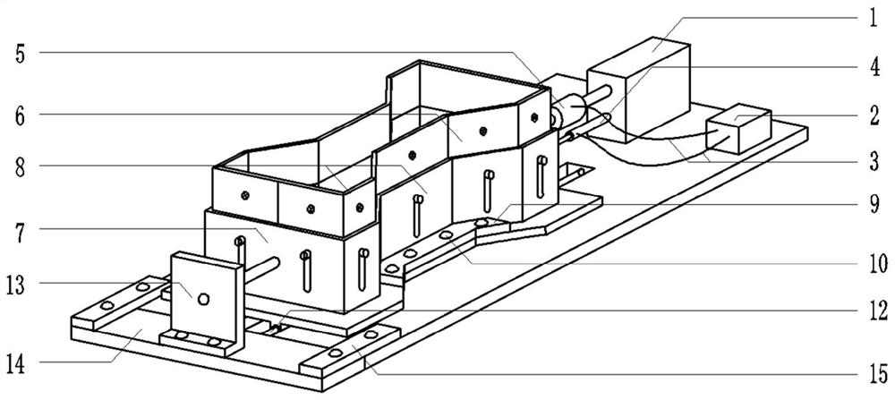
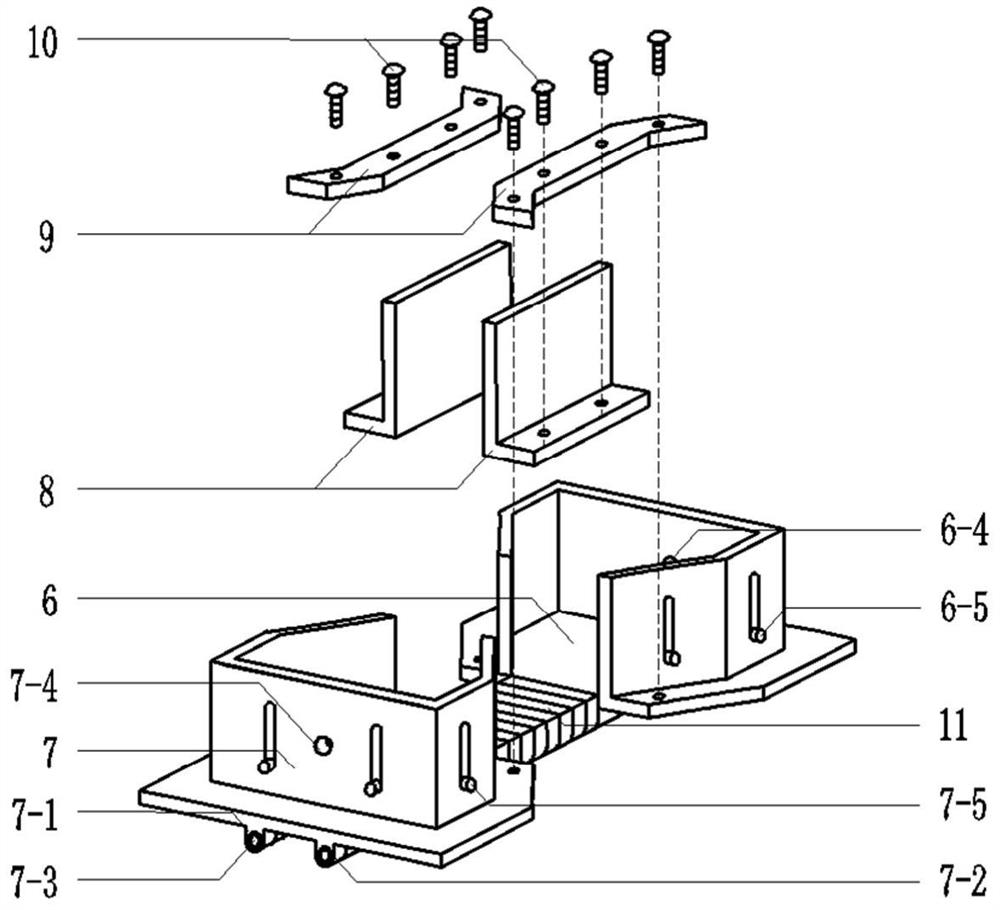
A height-adjustable soil uniaxial tensioning device with sliding rod

A uniaxial stretching, sliding rod technology, applied in the direction of measuring device, strength characteristics, preparation of test samples, etc., can solve the problems of eccentric stretching, large friction at the edge of the guide rail, and unstable rotation speed.

Active Publication Date: 2021-04-27
HOHAI UNIV
View PDF7 Cites 0 Cited by
  • Summary
  • Abstract
  • Description
  • Claims
  • Application Information

AI Technical Summary

Problems solved by technology

[0004] In the new test device developed by Che Ruijie et al., the guide rail is placed between the movable fixture and the test chassis, and the stretching of the sample is ensured by the sliding of the guide rail. This has the effect of reducing friction to a certain extent, but there will still be friction It has an impact on the experiment, because the guide rail acts as a limit movement to the movable fixture, so when eccentric stretching occurs, the friction on the edge of the guide rail will become greater
[0005] The strain-controlled horizontal uniaxial tensile instrument developed by Dang Jinqian et al. has a convenient test method and clear test results. However, since the handwheel is manually controlled, the rotation speed is not fixed, and it cannot solve the problem of re-tensioning the sample. Whether there will be eccentric stretching during stretching

Method used


Image

  • A height-adjustable soil uniaxial tensioning device with sliding rod
  • A height-adjustable soil uniaxial tensioning device with sliding rod
  • A height-adjustable soil uniaxial tensioning device with sliding rod

Examples


Embodiment Construction

[0058] The present invention will be further described in detail below in conjunction with the accompanying drawings and specific preferred embodiments.

[0059] In the description of the present invention, it should be understood that the orientations or positional relationships indicated by the terms "left side", "right side", "upper", "lower" are based on the orientations or positional relationships shown in the accompanying drawings, and are only For the purpose of describing the present invention and simplifying the description, rather than indicating or implying that the device or element referred to must have a specific orientation, be constructed and operate in a specific orientation, "first", "second" and the like do not represent components importance, and therefore should not be construed as limiting the invention. The specific dimensions used in this embodiment are only for illustrating the technical solution, and do not limit the protection scope of the present in...


PUM


Abstract

The invention discloses a height-adjustable soil uniaxial stretching device with a sliding bar, which comprises a bottom plate, a height-adjustable mold and a uniaxial stretching device; The two ends of the sample are clamped; including the fixed end of the mold, the tensile end of the mold, several sliding strips and two L bending plates; the fixed end of the mold, the tensile end of the mold and the bottom of each sliding strip are passed through two sliding The convex part is sleeved on the sliding rod in the two sliding grooves, and several universal balls are evenly arranged between the sliding convex part and the sliding rod; two L curved plates are spliced ​​on both sides of several sliding strips; the fixed end of the mold , the height of the stretching end of the mold and the two L bending plates can be raised and lowered; the uniaxial stretching device includes a fixed plate, a loader and a stress sensor. The invention can realize tensile tests on samples with different heights; and can avoid eccentric tension, and can quickly identify the breaking position of samples while reducing friction by sliding the strips.

Description

technical field [0001] The invention relates to a soil engineering test device, in particular to a soil uniaxial stretching device with adjustable height and a sliding bar. Background technique [0002] Soil is the product of rock weathering, and has certain shear strength, compressive strength and tensile strength in terms of mechanical properties. However, in engineering construction, the tensile strength of soil is basically not used by people, so when the predecessors studied the strength of soil, most of them ignored the tensile strength of soil. However, it is an unavoidable problem that soil bears tensile stress sometimes in engineering, and tensile stress often occurs around tall buildings. Therefore, in recent years, the problem of soil tensile strength has become more and more prominent, which has aroused people's wide interest. [0003] The test methods for measuring the tensile strength of soil mainly include: uniaxial tensile test, triaxial tensile test, soil ...

Claims


Application Information

Patent Timeline
Patent Type & Authority Patents(China)
IPC IPC(8): G01N3/08G01N3/06G01N3/04G01N3/02G01N1/28G01N1/36
CPCG01N1/286G01N1/36G01N3/02G01N3/04G01N3/06G01N3/08G01N2001/366G01N2203/0017G01N2203/0252G01N2203/0298
Inventor 孙一清沈振中张宏伟王鹏飞谈家诚李凡费照丹邹恒陈天浩蒯鹏程满健铭贺岩吴美子江兆强
Owner HOHAI UNIV
Why Eureka
Try Eureka