Height limiting equipment for bridge construction

A technology of bridge construction and height limit, applied in the direction of restricting traffic, roads, roads, etc., can solve the problems of damage to the height limit device, impact and impact of the height limit device, and achieve the effect of increasing stability and increasing friction.

Inactive Publication Date: 2020-11-27
潘屿芬
View PDF6 Cites 3 Cited by
  • Summary
  • Abstract
  • Description
  • Claims
  • Application Information

AI Technical Summary

Problems solved by technology

[0003] Based on the inventor's discovery above, the existing height-limiting equipment for bridge construction mainly has the following shortcomings. Passing by, and the goods loaded on the truck exceed the height of the truck itself, so

Method used


Image

  • Height limiting equipment for bridge construction
  • Height limiting equipment for bridge construction
  • Height limiting equipment for bridge construction

Examples


Embodiment 1

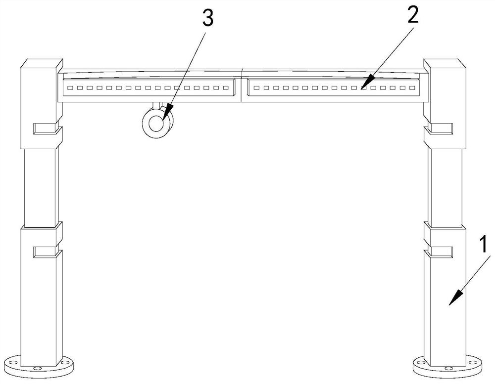
[0026] Example 1: Please refer to Figure 1-Figure 5 , the specific embodiments of the present invention are as follows:

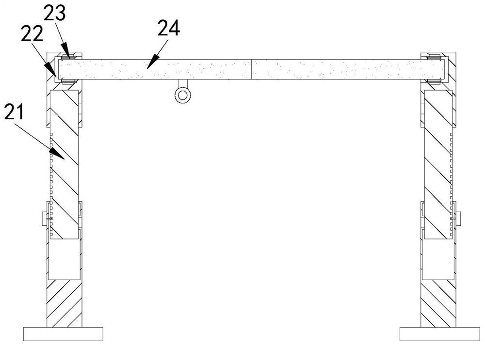
[0027] Its structure includes a supporting column 1, an intercepting device 2, and a warning light 3. The upper end of the supporting column 1 is engaged with an intercepting plate 2, and the warning light 3 is installed at the bottom of the intercepting device 2. The intercepting device 2 includes a telescopic Column 21, rotating groove 22, rewinding spring 23, intercepting plate 24, the top of described telescopic column 21 is provided with rotating groove 22, and described rewinding spring 23 is provided with two, and is arranged on the upper and lower sides of rotating groove 22 respectively. At the end, the intercepting plate 24 is engaged in the rotation groove 22 and is movably matched with the return spring 23 .

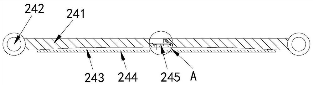
[0028] The intercepting plate 24 includes an intercepting plate body 241, a rotating shaft 242, a guide groove 243, a reflector 244, an...

Embodiment 2

[0032] Example 2: Please refer to Figure 6-Figure 8 , the specific embodiments of the present invention are as follows:

[0033] The engaging rod a3 includes a fixed ring a31, a spring seat a32, a rotating rod a33, and an engaging body a34. Both sides of the fixed ring a31 are provided with a spring seat a32, and the rotating rod a33 is engaged in the fixed ring a31 , the engaging body a34 is embedded in the side end of the fixed ring a31, and the two ends of the rotating rod a33 can rotate, which is beneficial for rolling in the spring groove a1.

[0034] The engaging body a34 includes a barb body b1, a roller b2, and a stabilizing block b3. The bottom of the barb body b1 is provided with four rollers b2, and the rollers b2 are engaged with the barb body b1. The stabilizing block b3 is embedded inside the barb of the barb body b1 , and the bottom end of the roller b2 protrudes from the inside of the barb body b1 , which facilitates the sliding of the barb body b1 on the int...


PUM


Abstract

The invention discloses height limiting equipment for bridge construction. The equipment structurally comprises a supporting column, an intercepting device and a warning lamp, an intercepting plate isclamped at the upper end of the supporting column; the warning lamp is mounted at the bottom end of the intercepting device; the intercepting device comprises a telescopic column, a rotating groove,a rewinding spring and an intercepting plate; the intercepting plate comprises intercepting plate bodies, a rotating shaft, a guide groove, a reflector and a clamping device; the clamping device comprises a spring groove, a reset spring, a clamping rod and a clamping groove; and the spring groove comprises a clamping block, a concave groove and a friction groove. According to the height limiting equipment, the two intercepting plate bodies are movably clamped with the rotating groove such that silt in a truck impacts a height limiting device, the height limiting device can be turned over through the intercepting baffle, the front impact of the silt on the height limiting device is avoided, and the height limiting device is prevented from being damaged.

Description

technical field [0001] The invention relates to the field of bridge construction, in particular to a height limiting device for bridge construction. Background technique [0002] The height limit of the bridge is to prevent the passage of large vehicles. The height limit equipment used at the construction site generally has the function of adjustment, so that it can adapt to the conditions of the construction site and allow large vehicles to pass. It can not only improve the practicability of the equipment, but also Allow construction vehicles to quickly enter the construction site to avoid delays in the construction period. [0003] Based on the inventor's discovery above, the existing height-limiting equipment for bridge construction mainly has the following shortcomings. Passing by, and the goods loaded on the truck exceed the height of the truck itself, so that when the truck passes the height-limiting device, the sand placed on the truck will hit the height-limiting de...

Claims


Application Information

Patent Timeline
IPC IPC(8): E01F13/00
CPCE01F13/00
Inventor 潘屿芬
Owner 潘屿芬
Why Eureka
Try Eureka