A self-adjusting immersive panoramic projection device
An automatic adjustment and projection device technology, which is applied to the frame of the engine, photography, wide-screen photography, etc., can solve the problems that the relative position of the projector cannot be adjusted, the projector cannot be collided or protected against dust, and the installation and fixation are troublesome. Achieve the effect of convenient transportation and carrying, ensuring stability and reducing floor space
- Summary
- Abstract
- Description
- Claims
- Application Information
AI Technical Summary
Problems solved by technology
Method used
Image
Examples
Embodiment 1
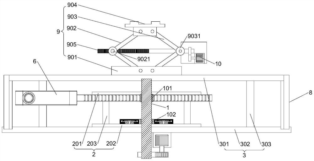
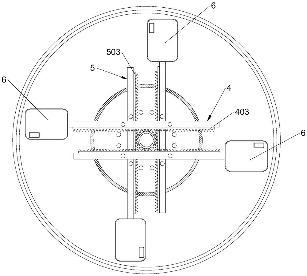
[0034] The self-adjusting immersive panoramic projection device of the present invention includes an inner casing 2, the inner casing 2 is provided with a rotating shaft 1, the rotating shaft 1 is provided with a first driving wheel 101 and a second driving wheel 102, and the inner casing 2 is provided with There are first sliding assemblies 4 respectively located on both sides of the first driving wheel 101, and the inner sidewalls of the two first sliding assemblies 4 are provided with first tooth plates 403 that mesh with the first driving wheel 101; There are second sliding assemblies respectively located on both sides of the second driving wheel 102, and the inner side walls of the two second sliding assemblies are provided with a second tooth plate 503 meshing with the second driving wheel 102; the first sliding assembly 4 and the second sliding assembly A projector 6 is installed at one end of the sliding assembly, and a power mechanism 7 is connected to the rotating sha...
Embodiment 2
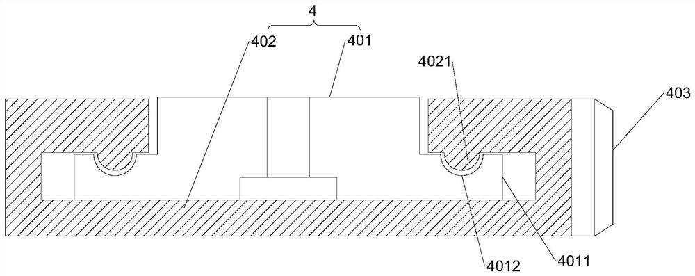
[0037] This embodiment is further optimized on the basis of Embodiment 1 as follows: the inner casing 2 includes a first upper casing 201, a first lower casing 202 and a first connecting column 203, and the first upper casing 201 and the first connecting column 203 The lower casings 202 are connected to each other through a plurality of first connecting columns 203 . The first sliding assembly 4 includes a first sliding seat 401 and a first sliding block 402, the upper end of the first sliding seat 401 is connected to the first upper casing 201, and flanges 4011 are provided on the lower ends of the two side walls of the first sliding seat 401 The upper end of the flange 4011 is provided with a first guide groove 4012, the two sides of the first slider 402 are bent upwards to form a first stopper located at the upper end of the flange 4011, and the lower end of the first stopper is provided with the first The guide groove 4012 fits with the first protrusion 4021 , and the firs...
Embodiment 3
[0040] This embodiment is further optimized on the basis of Embodiment 1 as follows: the first upper housing 201 is provided with a plurality of first threaded holes, and the first sliding seat 401 is provided with a first positioning position that can be aligned with the first threaded holes. The first positioning hole is equipped with a first fixing bolt.
[0041] After adopting the above-mentioned technical scheme: by opening several first threaded holes on the upper end of the first upper casing 201, the first sliding seat 401 is provided with a first positioning hole that can be aligned with the first threaded hole, and the first positioning hole is aligned with the first threaded hole. After the holes are aligned, the first fixing bolts are used to fix the first sliding seat 401 , so that the fixing and dismounting of the first sliding seat 401 is convenient, and meanwhile, the orientation of the first sliding seat 401 can be adjusted according to the actual situation.
PUM
 Abstract
Description
Claims
Application Information
 - R&D
- Intellectual Property
- Life Sciences
- Materials
- Tech Scout
- Unparalleled Data Quality
- Higher Quality Content
- 60% Fewer Hallucinations
Browse by: Latest US Patents, China's latest patents, Technical Efficacy Thesaurus, Application Domain, Technology Topic, Popular Technical Reports.
© 2025 PatSnap. All rights reserved.Legal|Privacy policy|Modern Slavery Act Transparency Statement|Sitemap|About US| Contact US: help@patsnap.com


