
An automatic fire extinguishing and warning mechanism for power distribution cabinets based on hydraulic engineering power transmission

A technology for power transmission and water conservancy engineering, which is applied in the substation/distribution device casing, substation/switchgear cooling/ventilation, electrical components, etc. problems such as the practicability of cabinets, to achieve the effect of improving fire extinguishing and reducing losses

Active Publication Date: 2022-04-29
广东海彬线槽有限公司
View PDF11 Cites 0 Cited by
  • Summary
  • Abstract
  • Description
  • Claims
  • Application Information

AI Technical Summary

Problems solved by technology

[0007] The purpose of the present invention is to provide an automatic fire extinguishing warning mechanism for power distribution cabinets based on hydraulic engineering power transmission, to solve the above-mentioned background technology and propose that the overall fire extinguishing effect of the existing power distribution cabinets is poor. The on-duty personnel must be required to manually extinguish the fire, which will not only easily cause the extension of the fire extinguishing time, but also cause the surrounding objects to catch fire because the fire cannot be extinguished in time, and it is not convenient to make a corresponding alarm reminder immediately when a fire occurs inside. Therefore, when the staff is not around, it cannot give a certain reminder to other people, thereby reducing the practicality of the power distribution cabinet

Method used


Image

  • An automatic fire extinguishing and warning mechanism for power distribution cabinets based on hydraulic engineering power transmission
  • An automatic fire extinguishing and warning mechanism for power distribution cabinets based on hydraulic engineering power transmission
  • An automatic fire extinguishing and warning mechanism for power distribution cabinets based on hydraulic engineering power transmission

Examples


Embodiment Construction

[0029] The following will clearly and completely describe the technical solutions in the embodiments of the present invention with reference to the accompanying drawings in the embodiments of the present invention. Obviously, the described embodiments are only some, not all, embodiments of the present invention. Based on the embodiments of the present invention, all other embodiments obtained by persons of ordinary skill in the art without making creative efforts belong to the protection scope of the present invention.

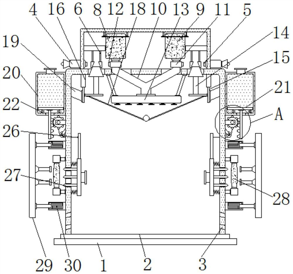
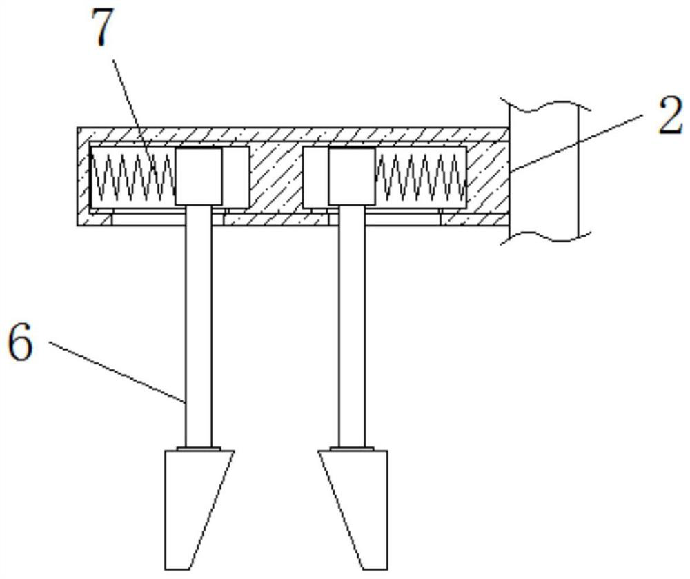
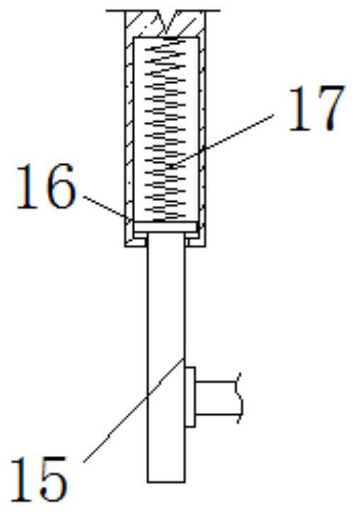
[0030] see Figure 1-7, the present invention provides a technical solution: an automatic fire extinguishing warning mechanism for a power distribution cabinet based on hydraulic engineering power transmission, including a base 1, a power distribution cabinet body 2, cooling holes 3, a warning horn 4, a start-stop switch 5, a squeeze Briquetting block 6, return spring 7, aluminum sulfate storage tank 8, sodium bicarbonate storage tank 9, flow tube 10, solenoid...


PUM


Abstract

The invention discloses an automatic fire extinguishing and warning mechanism for a power distribution cabinet based on hydraulic engineering power transmission, which includes a base, a power distribution cabinet body and cooling holes. The outer side of the switch is connected with an extrusion block, the inner side of the extrusion block is installed with an aluminum sulfate storage tank, the lower end of the flow tube is installed in the middle of the upper end of the air outlet plate, and the side of the air outlet plate is fixedly installed on the power distribution cabinet body Inside, the outer side of the baffle is equipped with a discharge port, and the outer end of the discharge port is fixedly installed on the inside of the dry powder storage room, the middle part of the circular gear is equipped with a transmission rod, and the outer side of the side airbag A buffer plate is installed. The automatic fire extinguishing warning mechanism of the power distribution cabinet based on the power transmission of water conservancy projects can take good fire extinguishing measures, minimize the loss caused by the fire, and at the same time, it can timely respond to the surrounding people when the fire occurs. Alarm reminder.

Description

technical field [0001] The invention relates to the technical field related to water conservancy projects, in particular to an automatic fire extinguishing and warning mechanism for a power distribution cabinet based on water conservancy project power transmission. Background technique [0002] Water conservancy projects refer to various projects such as flood control, drainage, hydropower generation, and water resource protection. However, in the process of water conservancy construction, a large number of electrical equipment and some machines that require electric power are required to perform auxiliary work on the construction site. The construction period of water conservancy projects is long, and some sites will set up temporary power distribution equipment for power transmission. As an important part of the power distribution equipment, the power distribution cabinet is an indispensable tool for power transmission. The internal temperature will continue to rise after ...

Claims


Application Information

Patent Timeline
Patent Type & Authority Patents(China)
IPC IPC(8): H02B1/56H02B1/30H02B1/32A62C3/16
CPCH02B1/565H02B1/30H02B1/32A62C3/16
Inventor 李凯龙
Owner 广东海彬线槽有限公司
Learn More