
Disclosed are air conditioner electric cabinet heat dissipation structure and air conditioner

A technology of heat dissipation structure and electric control box, which is applied to the structural parts of electrical equipment, details of space heating and ventilation, and household heating, etc., can solve the problems of complicated piping arrangement, increased cost of the whole machine, and impact on heat dissipation efficiency. , to achieve the effect of reducing cost, simple structure and high practicability

Pending Publication Date: 2020-11-27
GREE ELECTRIC APPLIANCES INC
View PDF0 Cites 0 Cited by
  • Summary
  • Abstract
  • Description
  • Claims
  • Application Information

AI Technical Summary

Problems solved by technology

[0003] The present invention solves the problem that the heat dissipation structure of the existing air-conditioning electric control box is highly dependent on the refrigerant cycle of the whole machine system through the main circuit of the system refrigerant pipe or the refrigerant flowing through the electric control box, and is easily affected by the blockage of the system refrigerant pipe. The life of control box components, complex pipeline arrangement, high demand for component types and quantities lead to technical problems that increase the cost of the whole machine, and propose a heat dissipation structure of the air conditioner electric control box and air conditioner with a simplified structure and low cost.

Method used


Image

  • Disclosed are air conditioner electric cabinet heat dissipation structure and air conditioner
  • Disclosed are air conditioner electric cabinet heat dissipation structure and air conditioner
  • Disclosed are air conditioner electric cabinet heat dissipation structure and air conditioner

Examples


Embodiment Construction

[0024] In order to make the technical problems, technical solutions and beneficial effects to be solved by the present invention clearer, the present invention will be further described in detail below in conjunction with the accompanying drawings and embodiments.

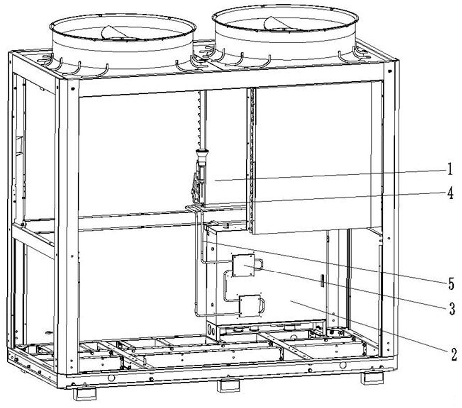
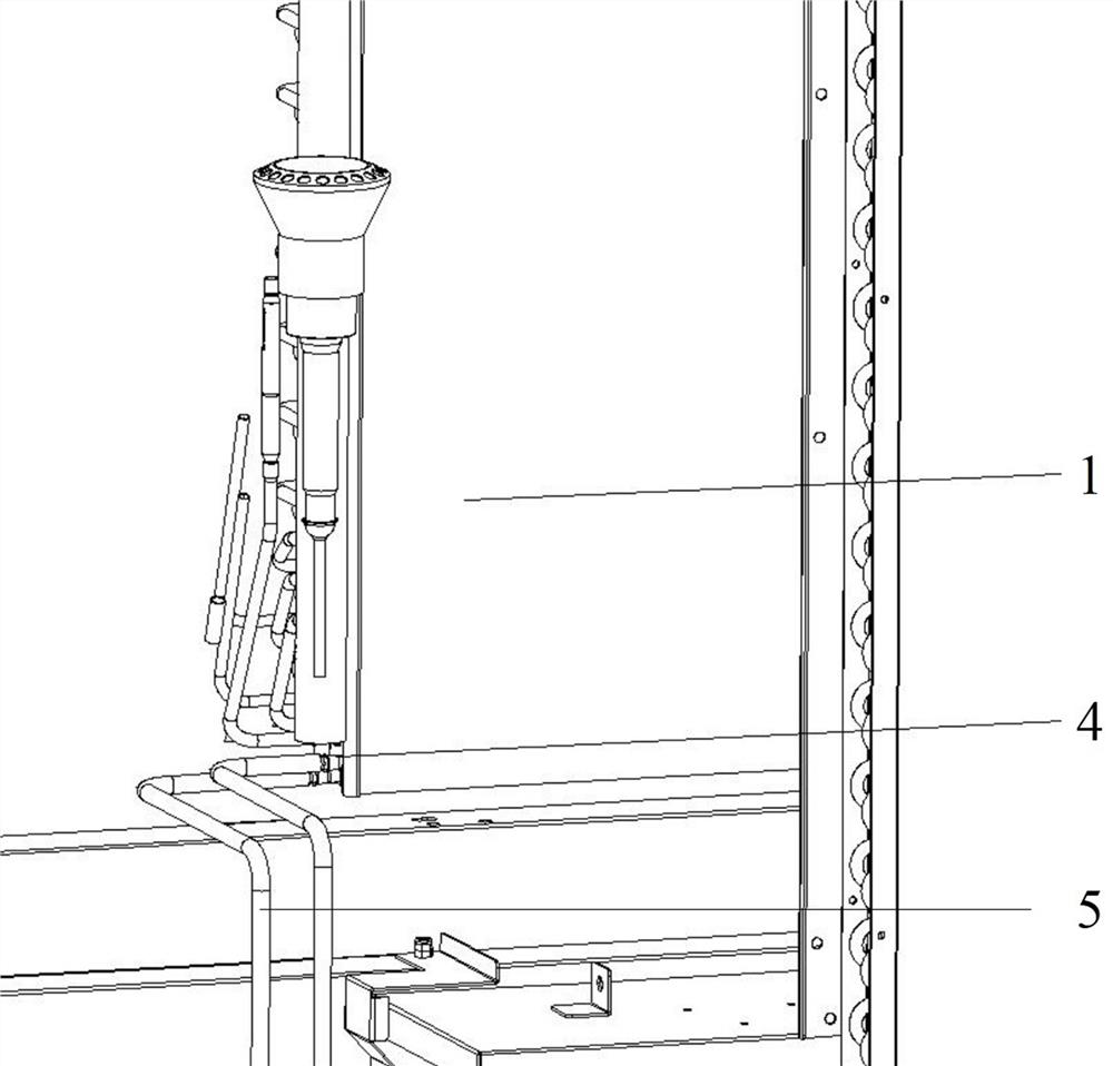
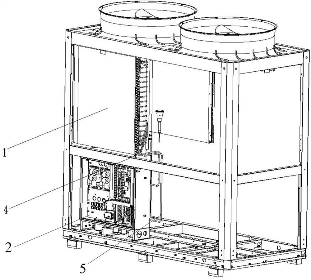
[0025] The following is attached Figure 1-6 And embodiment further illustrate the present invention.

[0026] The present invention provides a heat dissipation structure for an air conditioner electric control box, including a heat exchanger 1. As an embodiment, the heat exchanger 1 is an air-cooled finned heat exchanger, preferably a condenser, and its air-cooled fins are set In the air conditioning cooling duct.

[0027] Also comprise electric control box 2, on the shell of electric control box 2, preferably be provided with the radiator 3 of band closed cooling circuit on the back side of the shell of electric control box 2, this radiator 3 is aluminum radiator, also can It is a copper radiator 3; the radiato...


PUM


Abstract

The invention provides an air conditioner electric control box heat dissipation structure and an air conditioner, the air conditioner electric control box heat dissipation structure comprises a heat exchanger and an electric control box, a shell of the electric control box is provided with a radiator with a closed heat dissipation loop, and the closed heat dissipation loop extends into a heat dissipation air duct of the air conditioner. The invention provides an air conditioner electric cabinet heat dissipation structure and an air conditioner. A radiator of the air conditioner electric cabinet is connected with the last section of U-shaped pipe of the condenser to form a closed radiating loop filled with a refrigerant; the section of U-shaped pipe is independent from other pipelines of the condenser; a refrigerant releases heat in a U-shaped pipe in an upper-layer condenser of the pipeline system and dissipates heat through condenser fins, and absorbs heat in a pipeline in a radiatorof a lower-layer electric cabinet; the electric cabinet heat dissipation system is separated from the complete machine refrigeration and heating system without heat dissipation through a refrigerant pipeline of the complete machine system, so that the electric cabinet heat dissipation system is not influenced by the working state of the complete machine system, and the cost of the complete machineis reduced; meanwhile, the structure needs fewer pipelines, and is simpler in structure and higher in reliability and practicability.

Description

technical field [0001] The invention relates to the technical field of heat dissipation of an air conditioner electric control box, and more specifically relates to a heat dissipation structure of an air conditioner electric control box and an air conditioner. Background technique [0002] At present, the heat dissipation scheme of the electric control box of the air conditioner is mainly air-cooled heat dissipation or system refrigerant pipe heat dissipation. The use of air-cooled heat dissipation can satisfy the electric control box with low heat generation. For the frequency conversion unit industry, the system refrigerant pipe heat dissipation is generally used. Through the main road or bypass pipe of the system to the radiator of the electric control box, the refrigerant flows through the pipe to dissipate heat. This structural design makes the heat dissipation of the electric control box highly dependent on the refrigerant circulation of the whole system. Once the refr...

Claims


Application Information

Patent Timeline
Patent Type & Authority Applications(China)
IPC IPC(8): H05K7/20F24F13/30
CPCF24F13/30H05K7/20318H05K7/20327
Inventor 黎俊温祖恒罗伟新乔雨辰
Owner GREE ELECTRIC APPLIANCES INC
Learn More