Test tube rack capable of dynamically controlling evaporation capacity

A technology of dynamic control and test tube rack, which is applied in the field of laboratory equipment, can solve the problem of dynamic adjustment of drying wind that cannot test tube rack

Active Publication Date: 2020-12-01
浙江科恩实验设备有限公司
View PDF8 Cites 3 Cited by
  • Summary
  • Abstract
  • Description
  • Claims
  • Application Information

AI Technical Summary

Problems solved by technology

[0004] The present invention aims to overcome the problem in the prior art that the drying wind of the test tube rack cannot be dynamically adjusted, and provides a test tube rack capable of dynamically adjusting the drying wind of the test tube rack and dynamically controlling the evaporation

Method used


Image

  • Test tube rack capable of dynamically controlling evaporation capacity
  • Test tube rack capable of dynamically controlling evaporation capacity
  • Test tube rack capable of dynamically controlling evaporation capacity

Examples


Embodiment

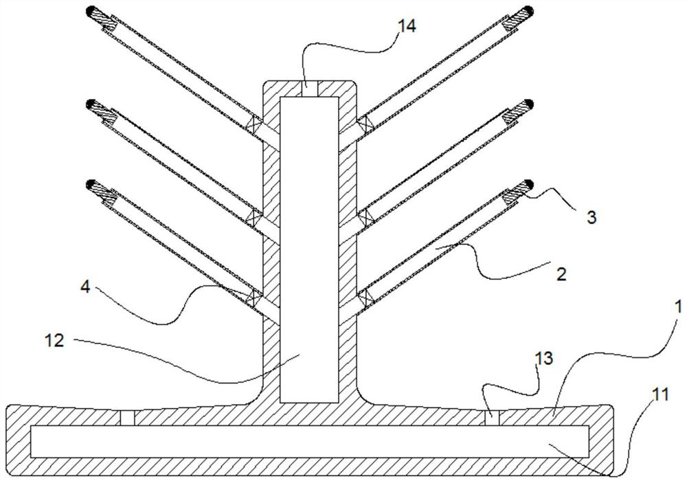
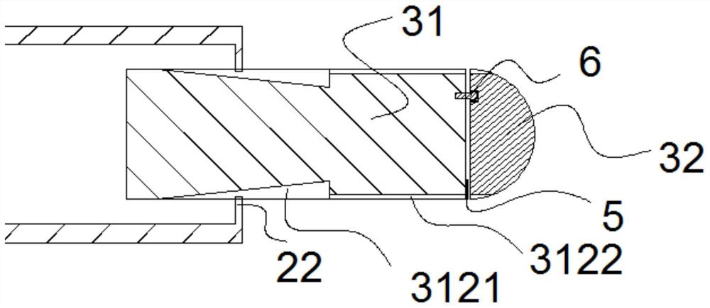
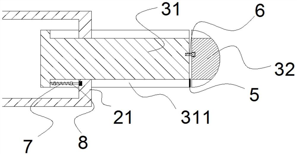
[0034] Embodiment: a kind of test tube rack of dynamic control evaporation, as figure 1 As shown, it includes an inverted T-shaped test tube rack support body 1, an air chamber 12 and a water collection chamber 11 are arranged on the support frame, a number of air outlets 121 are arranged on the air chamber, a support tube 2 is provided on the support frame, and one end of the support tube is connected to the outlet. The tuyere is connected, and the other end of the support tube is provided with a control plug 3, which can adjust the air volume flowing out from the control plug according to the weight of the test tube. Such as Figure 4 As shown, the control plug 3 is provided with a plug body 31 and a plug head 32, such as figure 2 and image 3As shown, the plug body is provided with a guide groove 311 which plays a guiding role and a control groove 312 for controlling the air volume, and the end of the plug body away from the support tube 2 is connected with a movable rod...


PUM


Abstract

The invention discloses a test tube rack capable of dynamically controlling evaporation capacity. The test tube rack comprises an inverted-T-shaped test tube rack supporting body, an air chamber and awater collecting chamber are arranged on a supporting frame, a plurality of air outlets are formed in the air chamber, a supporting pipe is arranged on the supporting frame, one end of the supportingpipe is connected with the air outlets, and a control plug is arranged at the other end of the supporting pipe and can adjust the air volume flowing out of the control plug according to the weight ofa test tube. The invention provides the test tube rack capable of dynamically controlling evaporation capacity, which can dynamically adjust dry air of the test tube rack. Air in the air chamber is blown into the supporting pipe through the air outlets and blown out of the control plug, the control plug can adjust the air outlet amount according to the weight of the test tube, the effect that a small test tube blows a small amount of air and a large test tube blows a large amount of air is achieved, and therefore the air outlet amount can be adjusted according to the test tube size.

Description

technical field [0001] The invention relates to the technical field of laboratory equipment, in particular to a test tube rack for dynamically controlling evaporation. Background technique [0002] At present, the test tube racks used in the market generally cannot adjust the drying force according to the size of the test tubes. The same drying force is used for both large and small test tubes, which leads to some problems. Small test tubes may be blown off, and unnecessary large air volume in the laboratory may cause safety accidents. If the air intake is small, it will take a long time for large test tubes to dry. [0003] Chinese patent publication CN103170389A, published on June 26, 2013, the name of the invention is an improved quick-drying test tube rack. The application includes the test tube rack body, which includes a bracket and a bottom plate. It is characterized in that: There is an upper cover, and there are multiple rows of jacks on the upper cover. The jacks ...

Claims


Application Information

Patent Timeline
IPC IPC(8): B01L9/06F26B9/10F26B21/00F26B21/06F26B21/12
CPCB01L9/06F26B9/10F26B21/004F26B21/06F26B21/12
Inventor 袁利军杨明昊陈权洪
Owner 浙江科恩实验设备有限公司
Why Eureka
Try Eureka